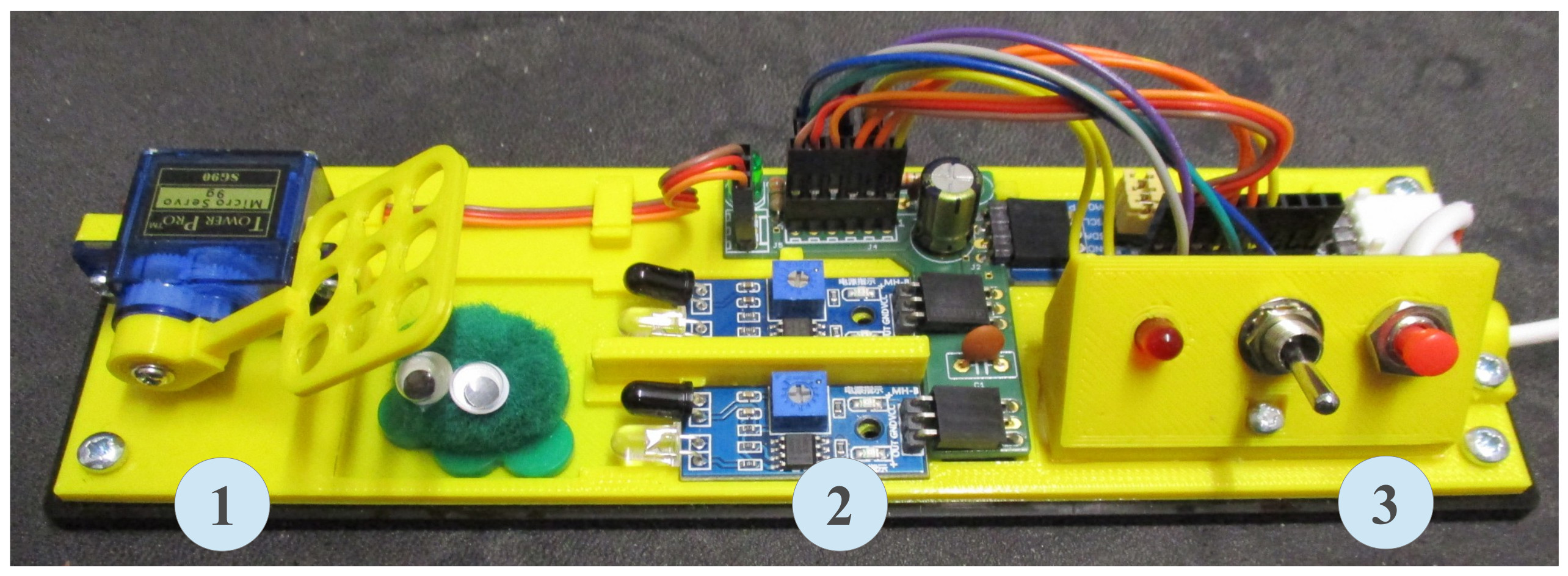
A new year, a new module, a new bug trap :). The original bug trap was made from recycled solenoids, the new bug trap is designed from scratch, with a focus on "reliability and maintainability", but also cost :). The scenario is again that the University is overrun with cockroaches and the students are required to design an automatic bug trap. The new hardware platform is shown in figure 1, having three main components :
Figure 1 : Bug trap
Off the shelf, in house hardware
Virtual wires
Lab 1 : combinatorial logic
Lab 2 : sequential logic
Lab 3 : simpleCPU_v1a, a software implementation
The bug trap's sensors (infra-red sensor modules and switches) and actuators (servo and LED) are interfaced to the FPGA using an PCF8574 I2C GPIO expander (Link), shown in figure 2. This was partly due to a need to reduce the size and thickness of the connecting cable, but mainly due to the the limited IO lines on the FPGA board used, we bought the wrong FPGA board :). Note, to reduce construction time this hardware is based on off-the-shelf Arduino modules.


Figure 2 : GPIO expander
The pin-outs are:
The acrylic base template and the 3D printed elements were designed in openScad, shown in figures 3 and 4. Note, the 3D printed base is used to mount / hold in place the various modules i.e. recessed inserts, owing to lack of mounting holes on the GPIO expander PCB etc. The model files can be downloaded here: (Link).
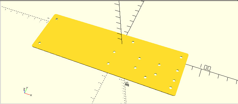
Figure 3 : Base
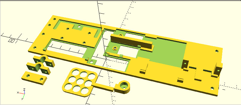
Figure 4 : 3D models
To reduce the amount of wiring needed to connect the various sensors and actuators to the GPIO expander, i made a small patch board as shown in figures 5 and 6. Plug J2 connects to the I2C expander, J5 connects to the servo. Plug J1 and J2 connect to switches, JP6 to front panel LED. Plug J3 and J1 connect to the infra-red sensor modules.
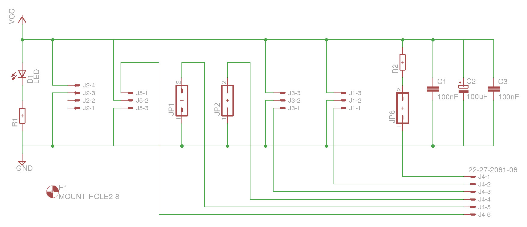
Figure 5 : interface circuit
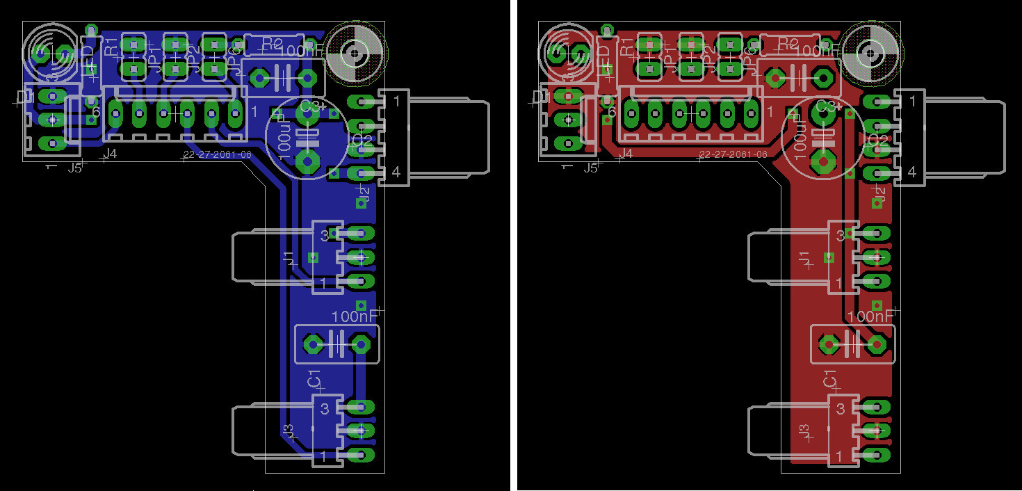
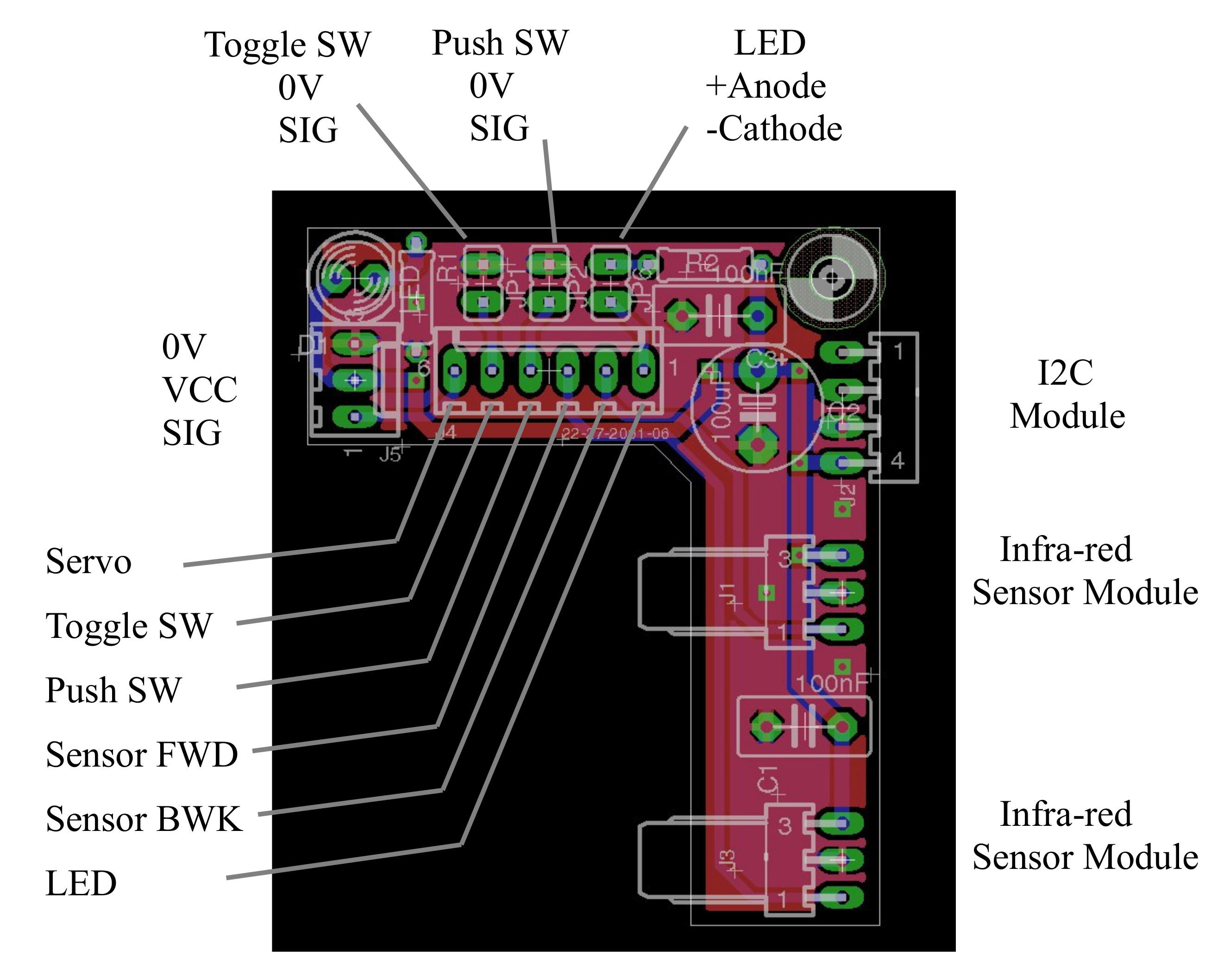
Figure 6 : Interface PCB
The aim of the practicals based on this hardware is to demonstrate the operation of basic logic gates, their functions and how these can be combined to implement different components i.e. the fundamental building blocks of a computer. In the previous bug trap labs this hardware was constructed using TTL gates (Link). With the change of curriculum we no longer teach hands-on electronics, therefore, i shifted logic gate teaching into an FPGA. Students can design and implement logic circuits as schematics, these are then synthesised and uploaded into the FPGA for testing. The top level schematic shown in figure 7, constructed from three components:
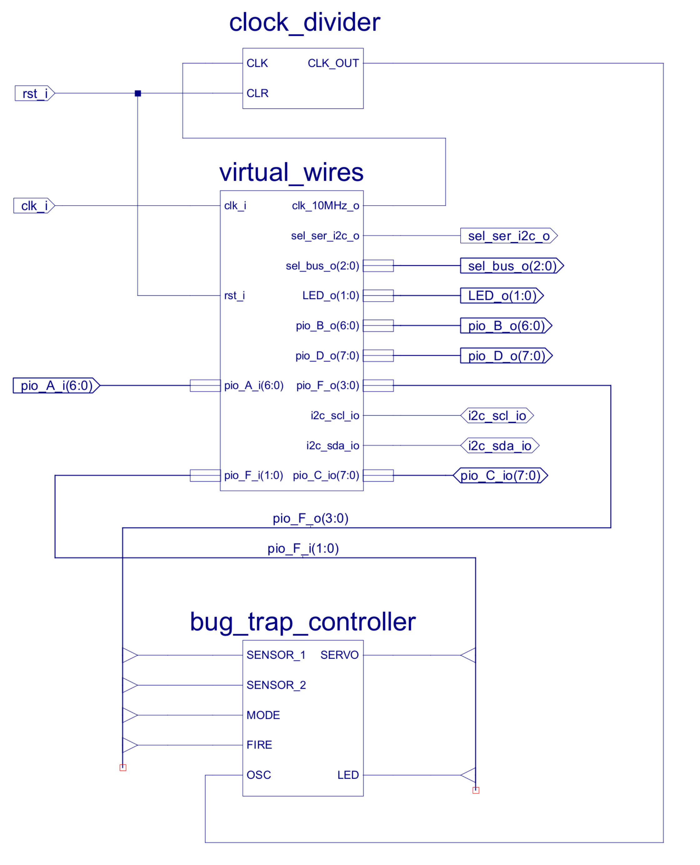
Figure 7 : top level schematic
To communicate data to and from the hardware a PicoBlaze system has been constructed and is integrated into the design using the virtual_wires component. This system provides the four inputs (pio_F_o) to the bug_trap_controller schematics and sends its two output (pio_F_i) signals to the hardware across the I2C bus shown in figure 8. The internals of the PicoBlaze system are shown in figure 9. Note, this system is used as a "black-box" component in the practical i.e. students only need to implement the control logic in the bug_trap_controller schematic.
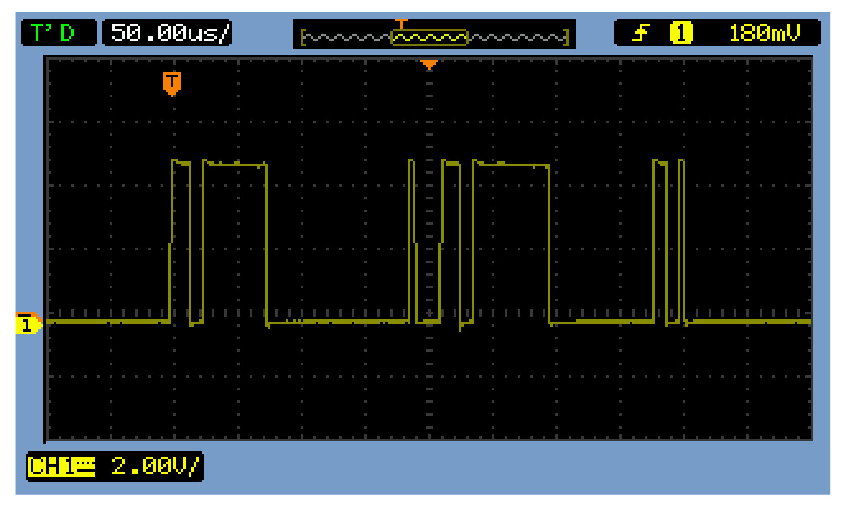
Figure 8 : I2C data packet
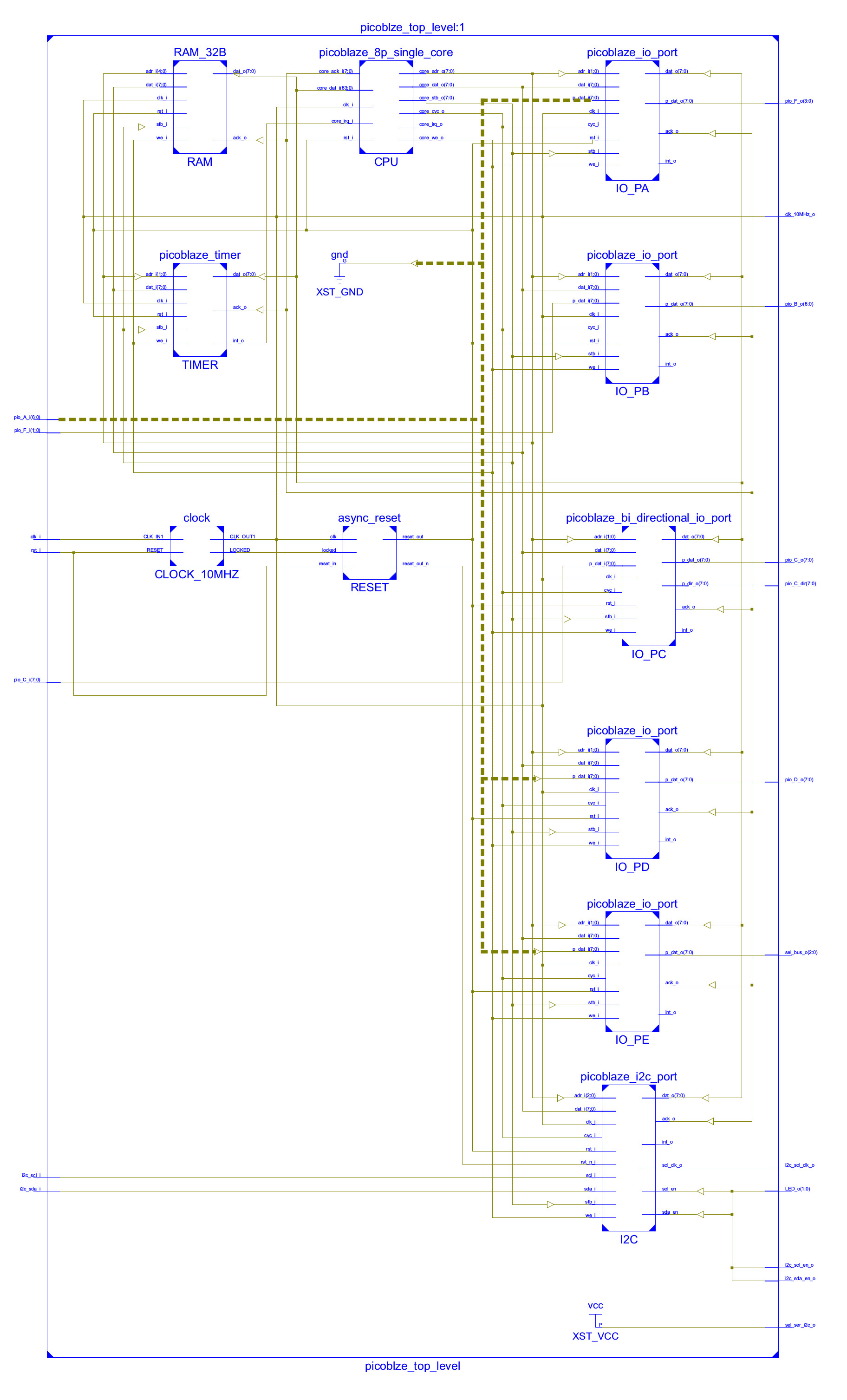
Figure 9 : PicoBlaze system
This first lab focuses on basic logic gates and simple combinatorial logic circuits. Therefore, the first bug_trap_controller is the simplest possible solution, only using the red push button as shown in figure 10, directly controlling the servo and LED. A short video is available here: (Link). The purpose of this design is to allow an initial test i.e. do the LED and servo work. With any hardware there is a chance that things will break, plugs fall out, wires break etc. Things only work perfectly in simulations :).
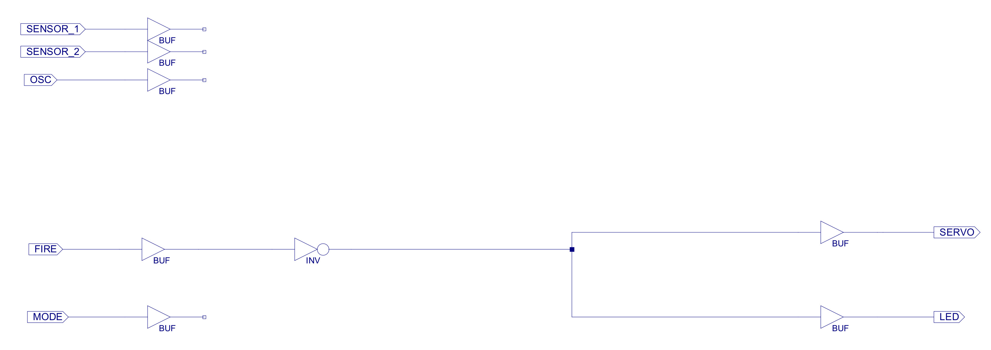
Figure 10 : Manual mode only
The second bug_trap_controller uses the infra-red sensors as shown in figure 11, a short video is available here: (Link). Again a chance to test the hardware i.e. the sensors / adjust their sensitivity, and to see if anyone can spot the NAND gate, and understand why we have so many buffers :)
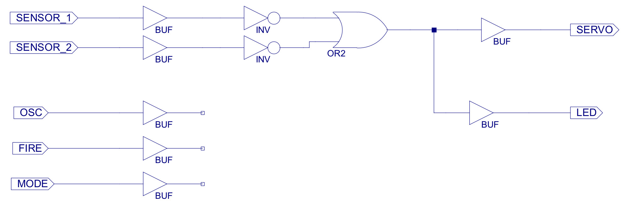
Figure 11 : Automatic mode only
The third bug trap now introduces the main design elements of this lab, how to combine the previous auto and manual modes, how to convert the pseudo code as shown in figure 12 into a combinatorial logic circuit.

Figure 12 : Bug trap control rules
To combine the automatic and manual control rules the toggle switch is used to select between the two behaviours i.e. a MODE switch, with the selected mode being indicated by the LED:
These control rules can be "rephrased" as shown in figure 13, or as the truth table as shown in figure 14, the aim here is to get across the ideas of basic logic functions, and that these can then be used to implement functional systems in the real world i.e. an AND gate is more than Boolean algebra.
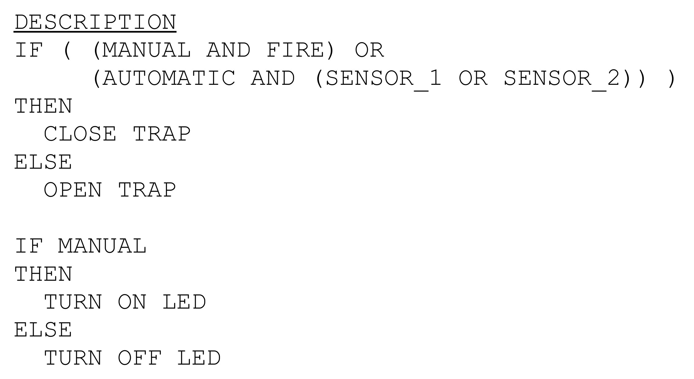
Figure 13 : Updated control rules
The twist in the design is that students typically infer positive logic when reading these rules i.e. assume that when the FIRE button is pressed its associated signal will output a logic 1 else a logic 0. However, this is not the case. Only the actuators use positive logic, all sensors/switches use negative logic, are active low, as shown in the truth table in figure 14. A sensor's TRUE state is represented by 0V, the FALSE state is represented by +5V. Why? Answer, it made the hardware/electronics easier to build and it teaches students not to make assumptions, always check, check and check again :).
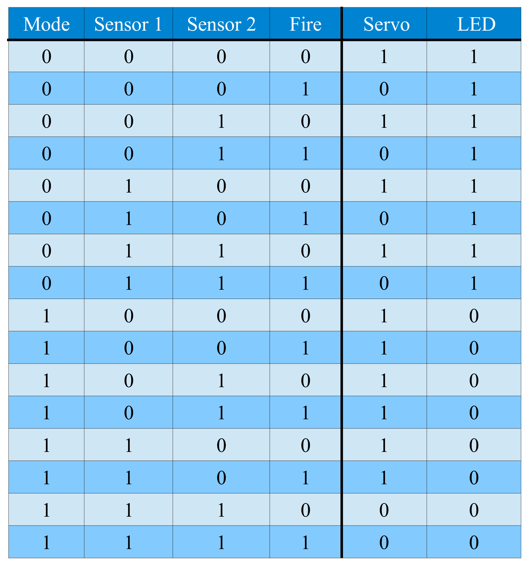
Figure 14 : Truth tables
The rules defined by this truth table can be implemented using the logic circuit shown in figure 15.
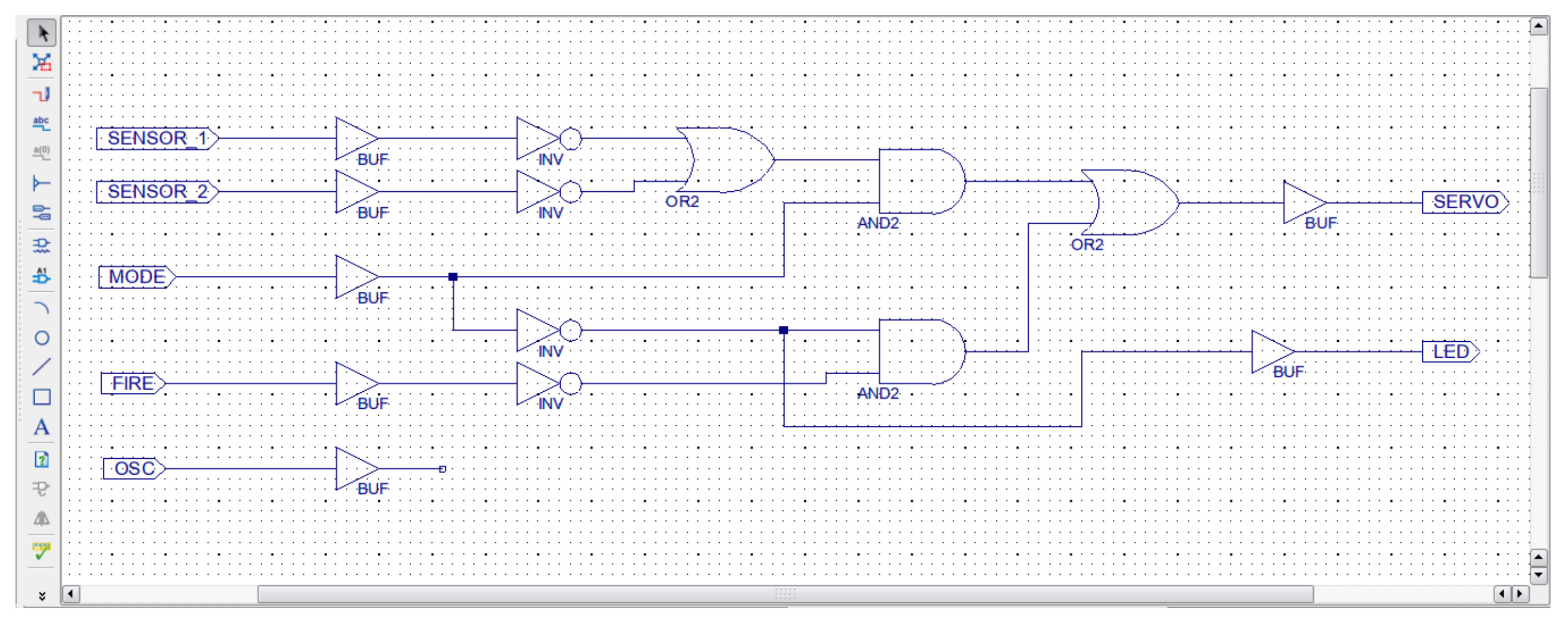
Figure 15 : Control logic
A short video of the trap implementing the manual and automatic modes is available here: (Link)(Link).
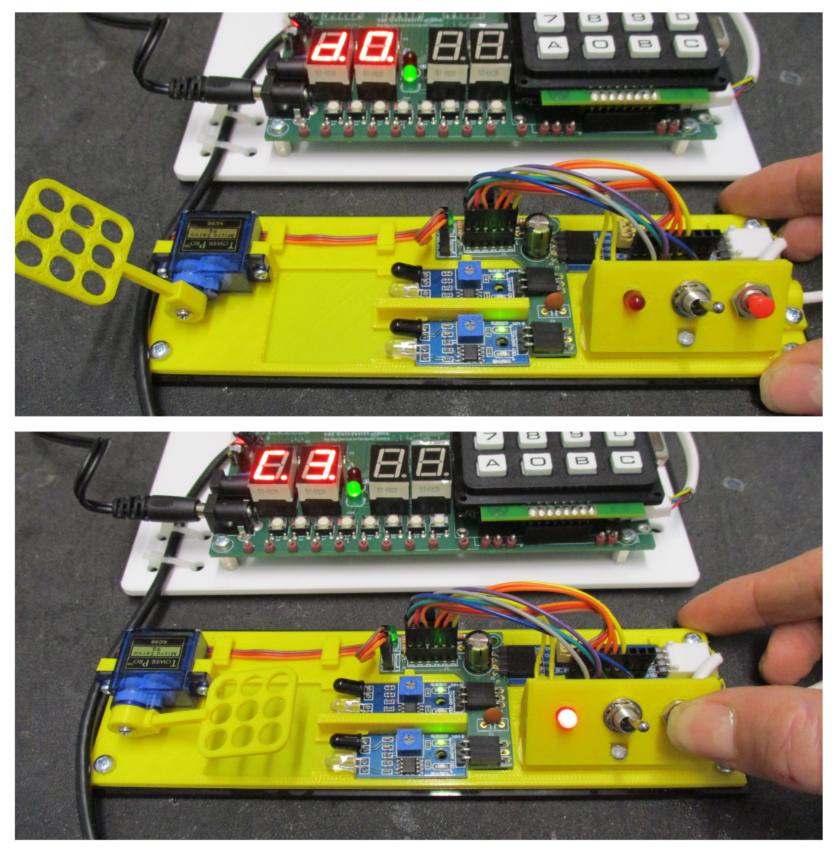
Figure 16 : Testing, manual mode (top), triggered (bottom)
The fourth bug_trap_controller implements the manual and automatic modes, but also uses the infra-red sensors to detect the size of the bug. In automatic mode if the bug is small and only triggers one sensor the trap is triggered lowering the net, holding the bug. However, if the bug is larger, or tries to push through the trap and triggers both sensors the trap enters "persuade" mode, repeatedly hitting the bug. The pseudo code for this new behaviour is shown in figure 17.
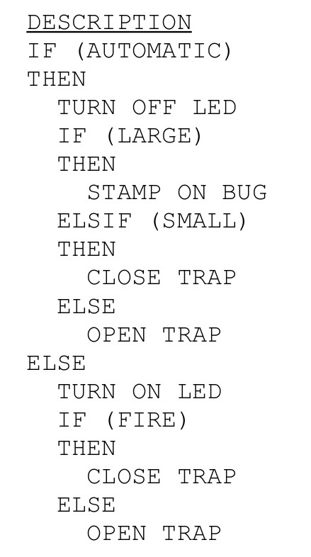
Figure 17 : Auto, Manual and Persuade rules
This controller could be implemented in a number of different ways, but to start to introduce hierarchical design / component reuse etc, they are asked to implement this system using bit multiplexers, as shown in figure 18. Then complete the circuit shown in figure 19.
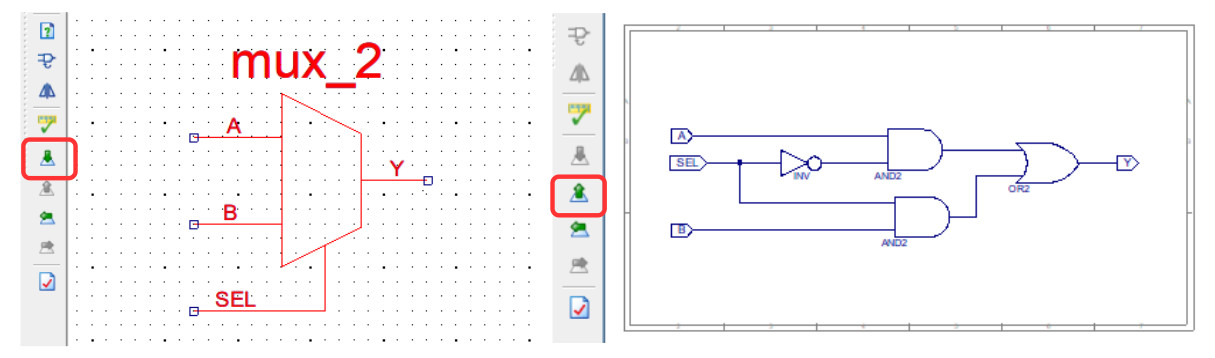
Figure 18 : bit multiplexer, symbol (left), schematic (right)
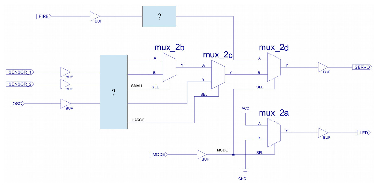
Figure 19 : bit multiplexer based solution
One possible solution is shown in figure 20. To state the obvious its not a very good solution :), lots of redundant elements that can be removed. However, the intention of using this approach is to make the link between the IF-THEN-ELSE statements in pseudo code and implementing these in hardware as multiplexers (MUX) i.e. each IF is a MUX. This simple solution then introduces the ideas of logic minimisation, optimisation i.e. the realisation that in logic design you can implement a solution that contains redundant components e.g. MUX_2B, that can then be removed. A short video is available here: (Link).
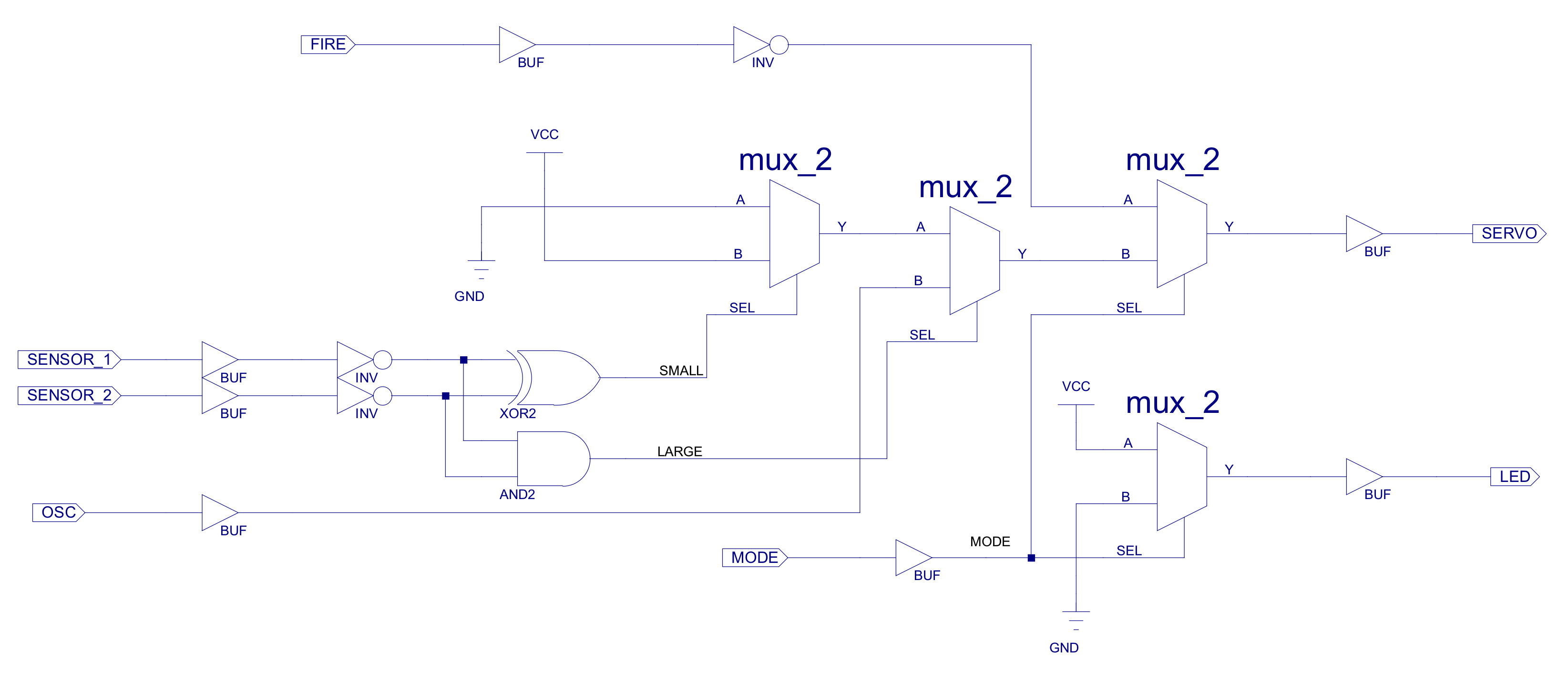
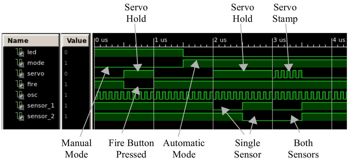
Figure 20 : Auto, Manual and Persuade mode, schematic (top), simulation (bottom)
In lab 2 we induction memory elements i.e. flip-flops to our digital design toolkit. To support this the back story is updated, the cockroaches have evolved, they have learnt to only partially enter the trap, if the trap then closes they can now pull themselves out i.e. wriggle backwards. To allow the operator to detect when this has occurred each trap needs to remember if either of the sensors have been triggered during the night. We need some memory devices, Flip-Flops :). Note, the secondary aim of this lab is to introduce the final set of components needed to build the simpleCPU processor in lab 3 i.e. logic + memory = computer.
We start with the simplest flip-flop, a set/reset (SR) flip-flop.
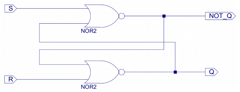
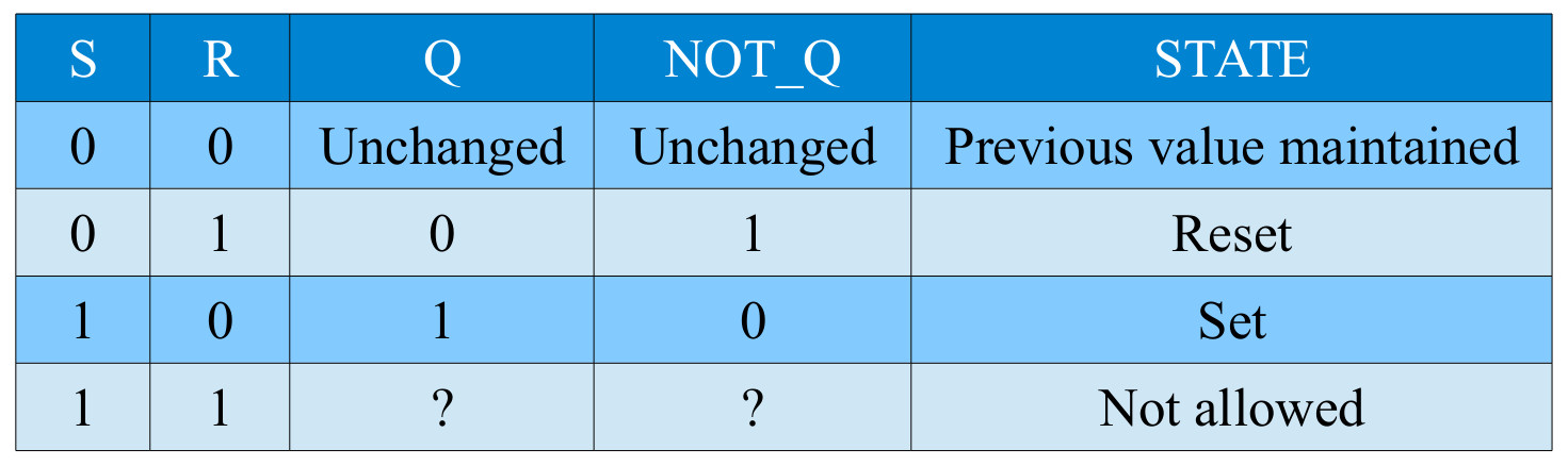
Figure 21 : SR flip-flop
This circuit can be converted into the component: SR_FF, and added to the existing Automatic-only bug trap controller shown in figure 11, the resulting solution is shown below (figure 22). Now when a bug enters the trap the SET lines on the SR flip-flop is toggled, setting the Q output to a logic 1, energising (turning on) the LED. Unlike the previous Automatic-only solution, now when the bug leaves the trap the LED will remain on until the RESET lines is pressed i.e. the RED push button. A short video is available here: (Link).
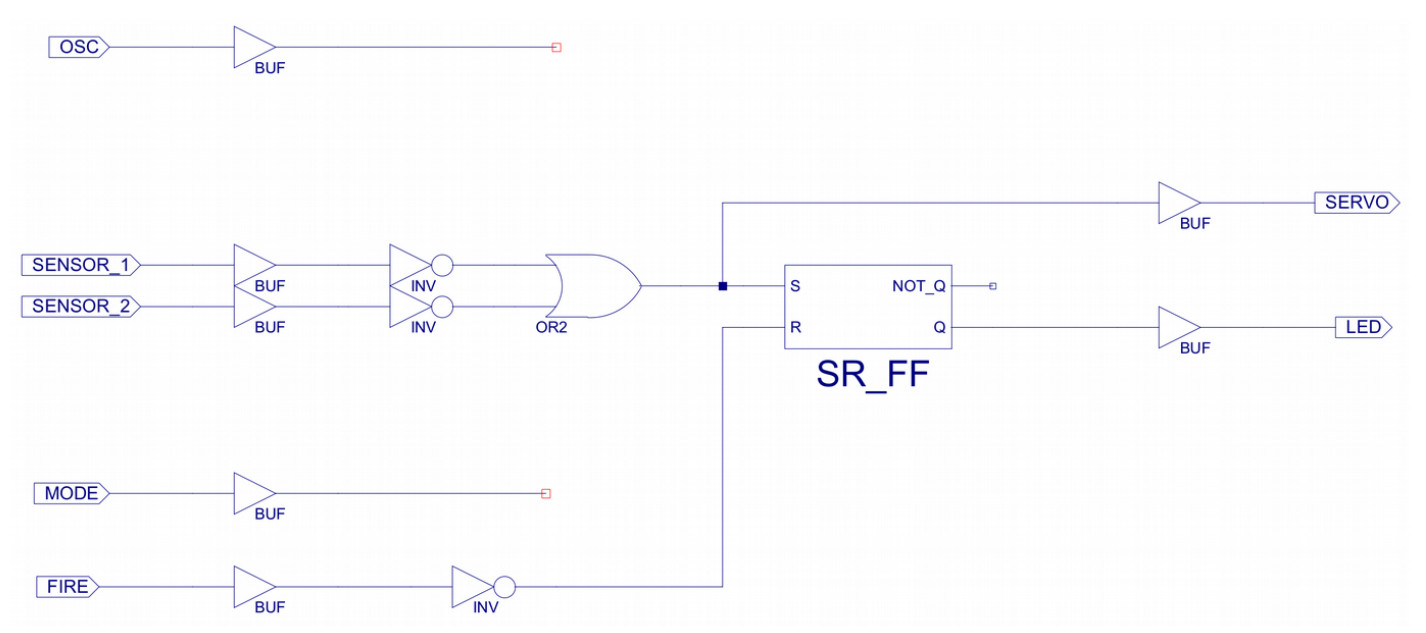
Figure 22 : automatic bug trap, with bug detected LED
The back story continues :). Unfortunately the bug traps have proven too “effective” and a number of operators have had their fingers crushed whilst trying to bait this trap. Therefore, the front panel toggle switch will now be used as an enable (safety) switch :
To indicate the trap status the LED function will also be updated :
This behaviour can be described by the rules shown in figure 23.
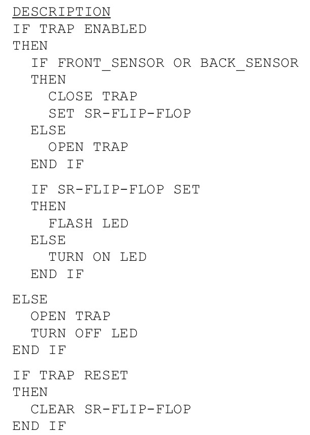
Figure 23 : New and improved, safe rules
The flashing functionality can be implemented in a number of different ways, but to introduce a new flip-flop the solution used is based on D-type flip-flops, as shown in figure 24. Note, this is also the primitive flip-flop element used in an FPGA slice i.e. default building block within the FPGA.
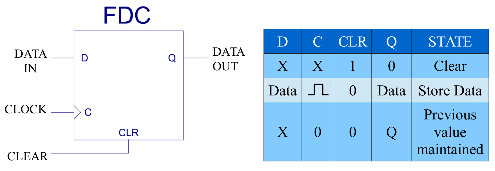
Figure 24 : D-type Flip-flop
To minimise the size of the circuits that the students needed to draw the top level schematic provides a 0.8Hz clock, sourced from the on-board oscillator. To minimise the complexity of the circuit used to generate the flashing / alternating signal, a simple ring counter is used, as shown in figure 25. This circuit is a one-hot counter i.e. counts from 0 to 2 using a one-hot representation. Therefore, if the LED is connected to any of its outputs, the LED will turn on for one clock cycle and off for two clock cycles i.e. on for approximately 1 second and off for 2 seconds.

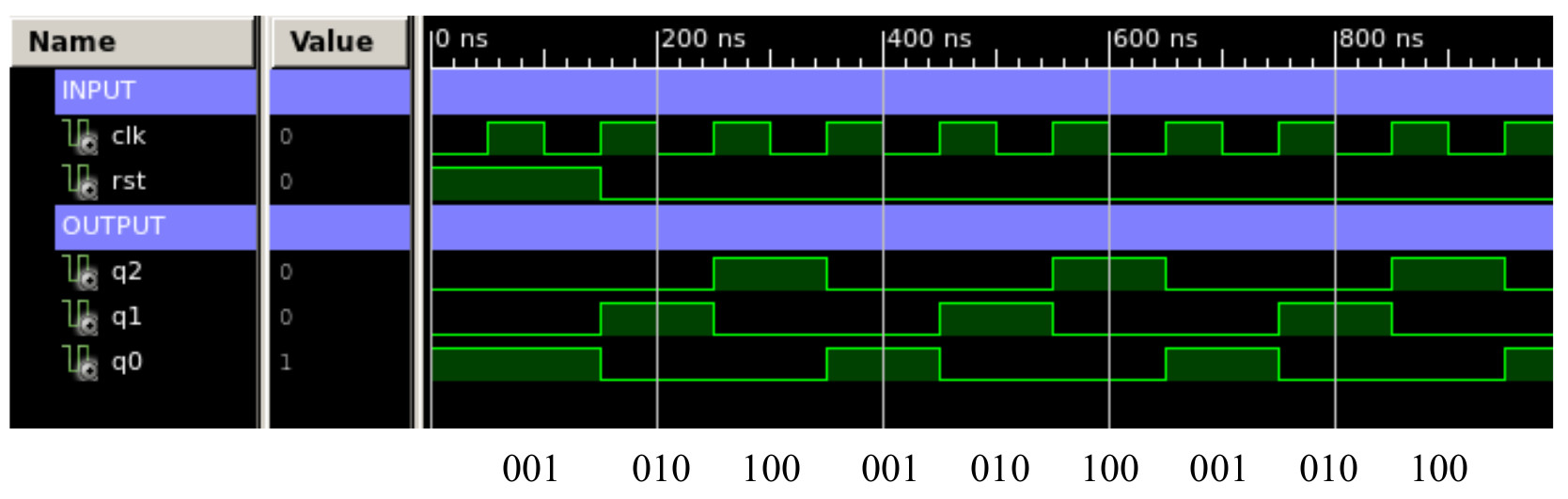
Figure 25 : Ring counter, schematic (top), simulation (bottom)
Again the ring counter schematic can be converted into a component: ring_counter_3, and added to the bug trap controller as shown in figure 26. A short video is available here: (Link).
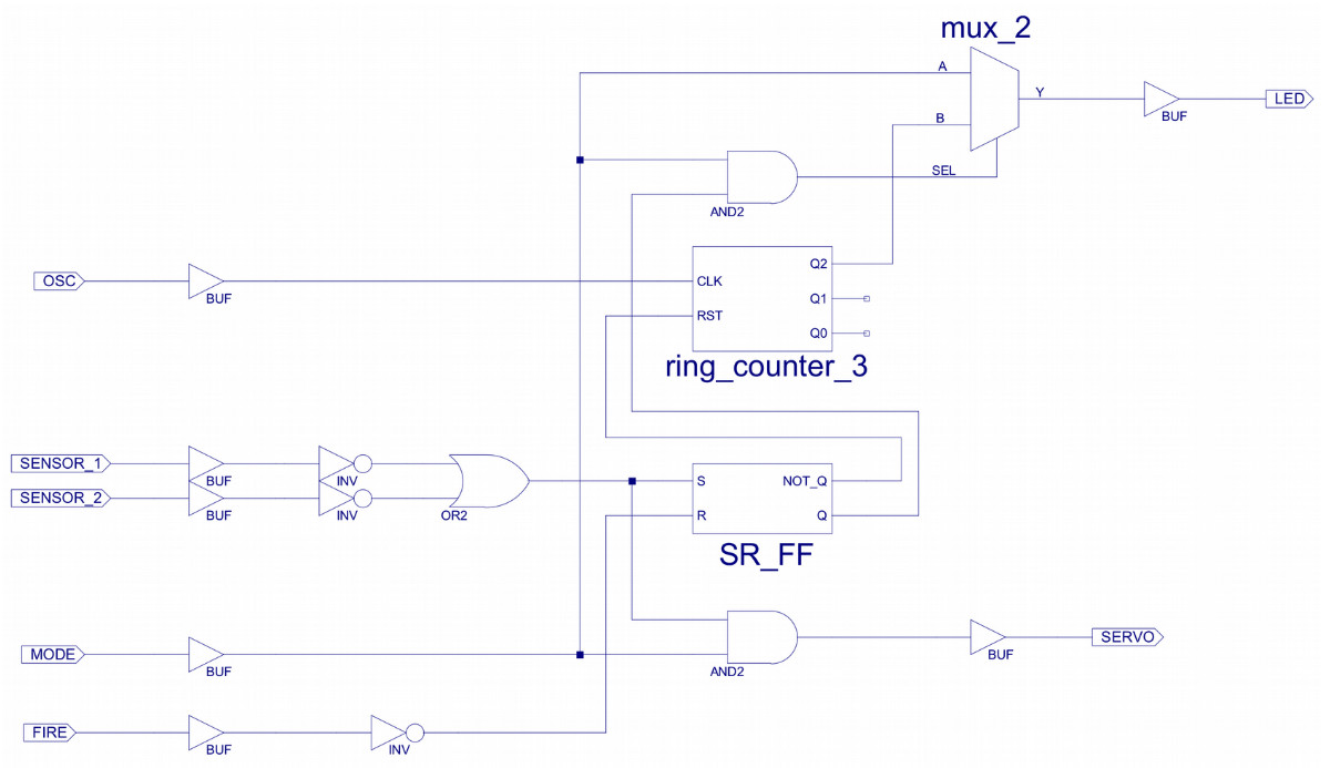
Figure 26 : New and improved, safe bug trap controller
The back story evolves again :), to "counter" the new breed of super cockroaches (the ones that can wriggle backwards) the trap's control rules have again been updated, as shown in figure 27, such that the net is only closed when the cockroach has been in the trap for approximately 4 seconds. In the previous version, the trap closes too early, such that the cockroach is only be partially in the trap i.e. the net only traps its head. Therefore, delaying the trigger allows the cockroach time to move into the middle of the trap and to start eating the bait, such that when the net closes it captures the whole cockroach.
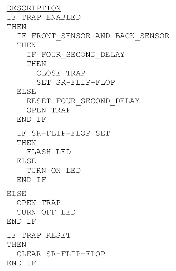
Figure 27 : New wait and see rules
To implement this delay the 0.8Hz clock is used to clock a binary counter i.e. if the count value is allowed to count up to 5 a four second delay will have elapsed. This binary counter can be implemented in a number of different ways, but to show some component reuse it will be constructed from components developed in other labs i.e. a ripple adder and a registers, as shown in figure 28.
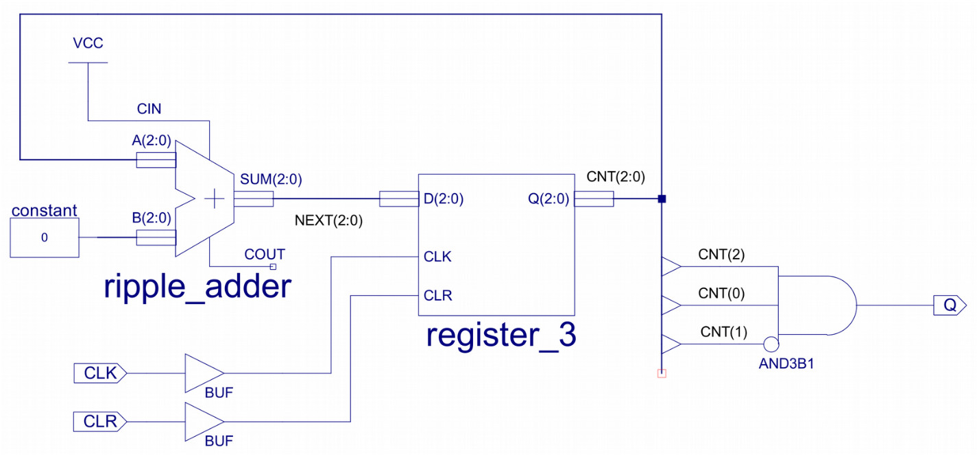
Figure 28 : binary counter
Again, this schematic can be converted into a component: delay_4_sec, and added to the previous bug_trap_controller schematic, as shown in figure 29. A short video is available here: (Link).
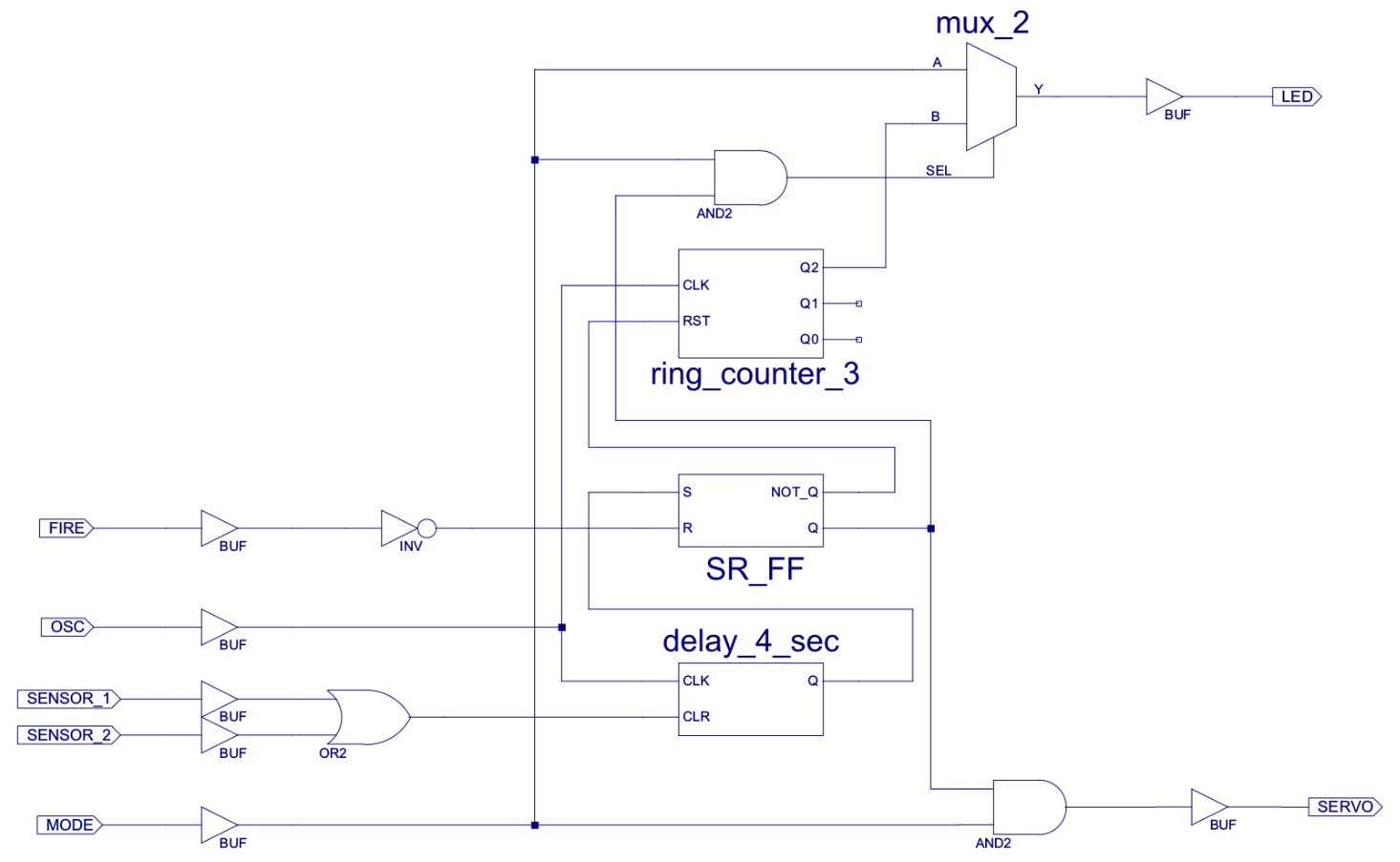
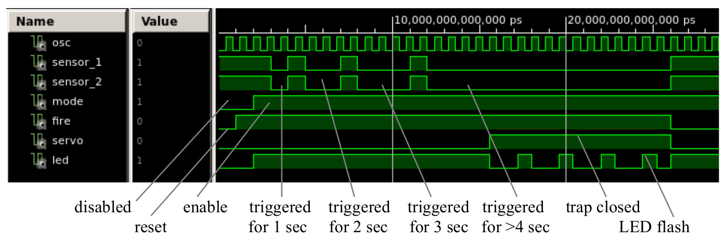
Figure 29 : New wait and see rules schematic (top), simulation (bottom)
The third lab in this series replaces the hardwired bug trap controller i.e. the applications specific hardware, with a general purpose processor. The aim here is to show the flexibility of moving functionality into software, and to also highlight the hardware costs in doing this. Note, also the processing performance costs in doing this i.e. time. The processor used is the simpleCPU_v1a that is discussed and designed in supporting lectures. For more information refer to: (Link). The hardware used to implement this processor is derived from the components used to construct the previous bug trap i.e. logic + memory = computer. The top level schematic of the new computer controlled bug trap is shown in figure 30.
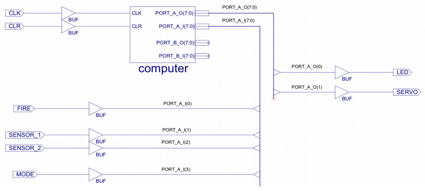
Figure 30 : computer controlled bug trap
Inside this top level component is the simpleCPU_v1a processor, memory and general purpose input/output ports (GPIO), as shown in figure 31. Note, this design has two GPIO ports: A and B, giving 16 input lines and 16 output lines, this is a lot more IO than we need for the bug trap controller, but was included to make a more interesting memory map.
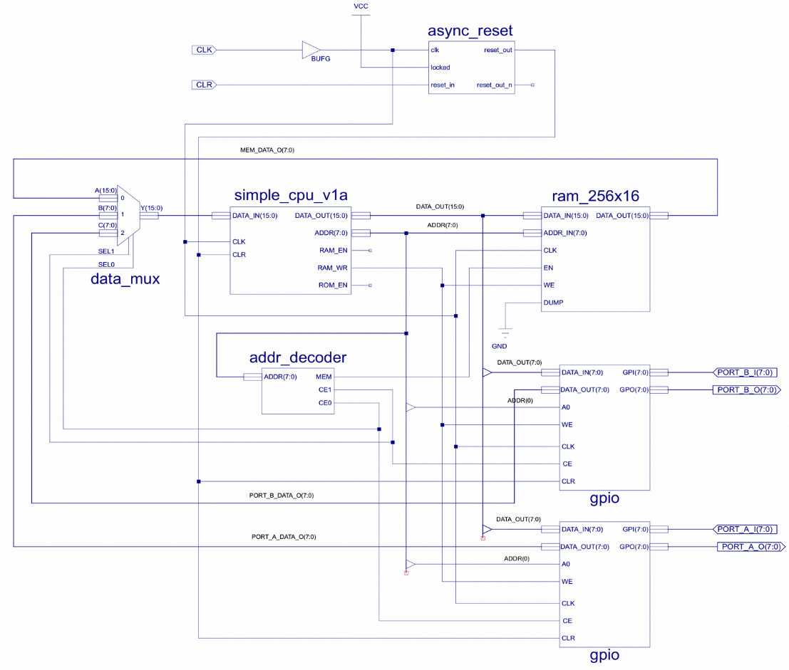
Figure 31 : computer architecture
The internal architecture of the simpleCPU processor is shown in figure 32.
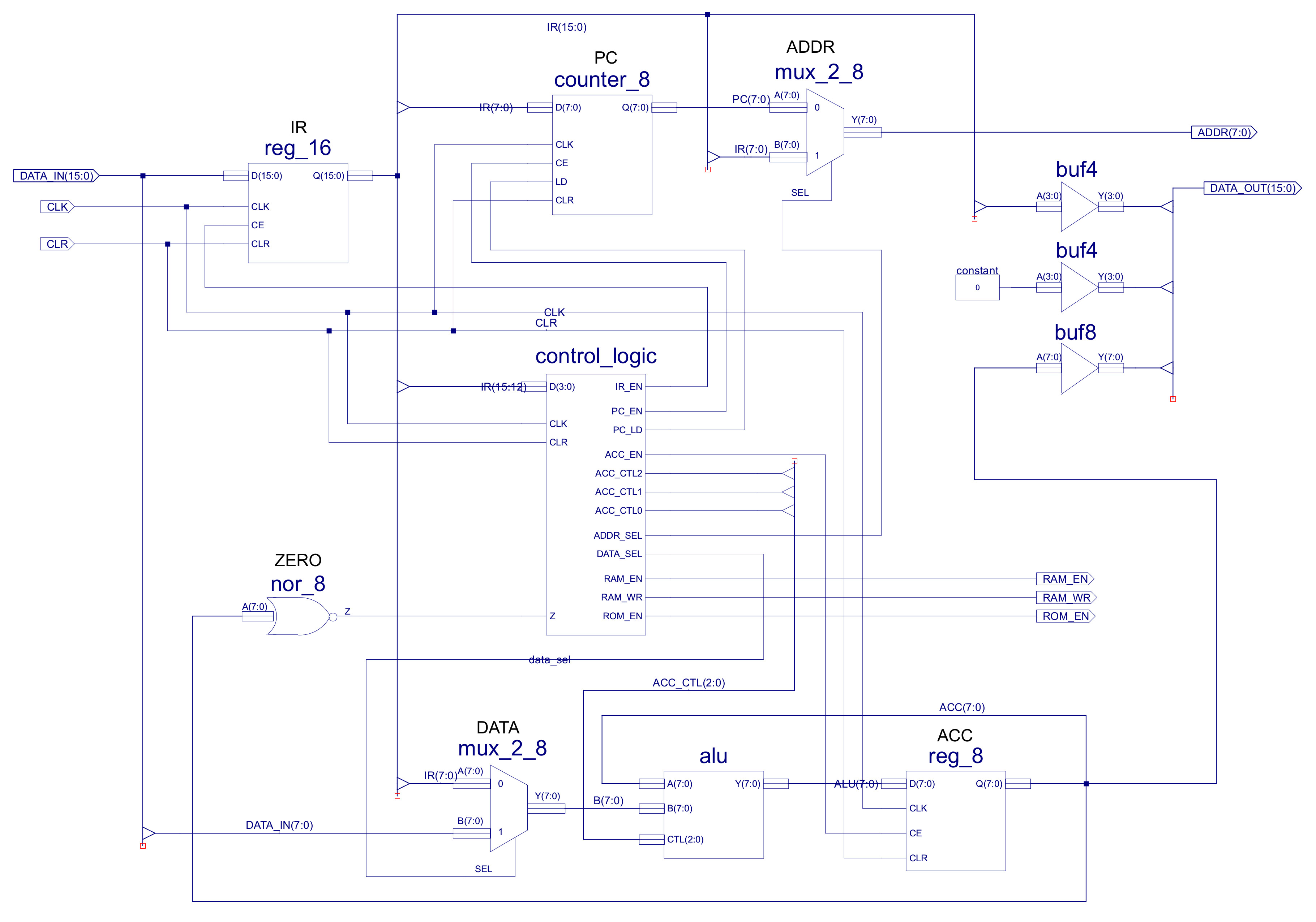
Figure 32 : simpleCPU_v1a architecture
The GPIO lines are memory mapped into the top of the processors address space as shown in figure 33. To control the bug trap the program needs to access the four inputs (2 x sensors + 2 x switches) and control the two outputs (LED + servo). These 6 GPIO lines are connected to port A, as listed in figure 34.
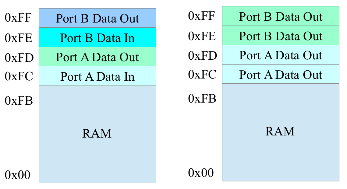
Figure 33 : computer controlled bug trap memory map
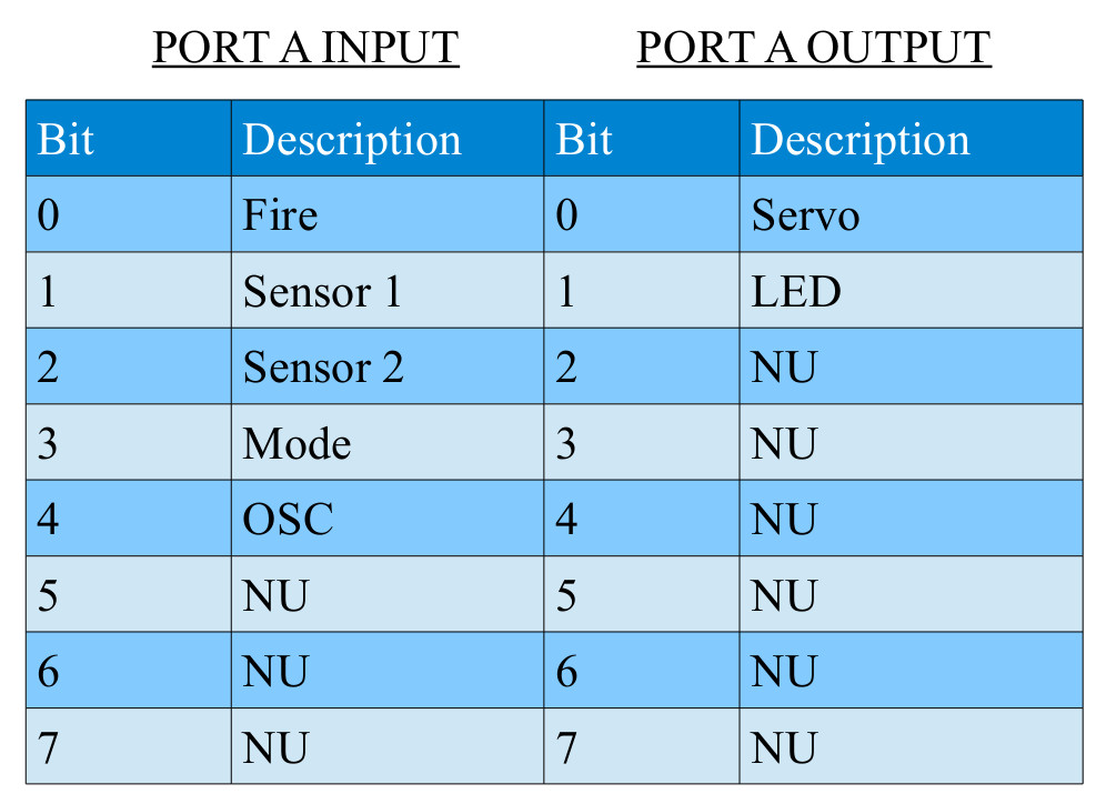
Figure 34 : port A pin assignment
To control the bug trap the following code can be used to re-implement the previous hardwired control rules i.e. Auto, Manual and Persuade (stamp) modes. The simulation of this new system is shown in figure 35.
DESCRIPTION                 ASSEMBLER CODE
-----------                 --------------

IF (AUTOMATIC)              start:
THEN                            move 0x00
  TURN OFF LED                  store 0xFC
  IF (LARGE)
  THEN                      loop:
    STAMP ON BUG                load 0xFC
  ELSIF (SMALL)                 and 0x08
  THEN                          jumpnz manual
    CLOSE TRAP
  ELSE                      auto:
    OPEN TRAP                   move 0xFF
  ENDIF                         subm 0xFC
ELSE                            and 0x06
  TURN ON LED                   jumpz start
  IF (FIRE)                     sub 0x06
  THEN                          jumpz large
    CLOSE TRAP
  ELSE                      small:
    OPEN TRAP                   move 0x01
  ENDIF                         store 0xFC
ENDIF                           jumpu loop

BIT  FUNCTION               large:
-------------                   move 0x00
0    FIRE                       store 0xFC
1    SENSOR1                    load 0xFC
2    SENSOR2                    and 0x06
3    MODE                       jumpnz loop
4    OSC
                            waitLow:
                                load 0xFC
                                and 0x10
                                jumpz waitLow
                                move 0x01
                                store 0xFC

                            waitHigh:
                                load 0xFC
                                and 0x10
                                jumpnz waitHigh
                                jumpu large

                            manual:
                                load 0xFC
                                and 0x01
                                jumpz fire

                            reset:
                                move 0x02
                                store 0xFC
                                jumpu loop

                            fire:
                                move 0x03
                                store 0xFC
                                jumpu loop
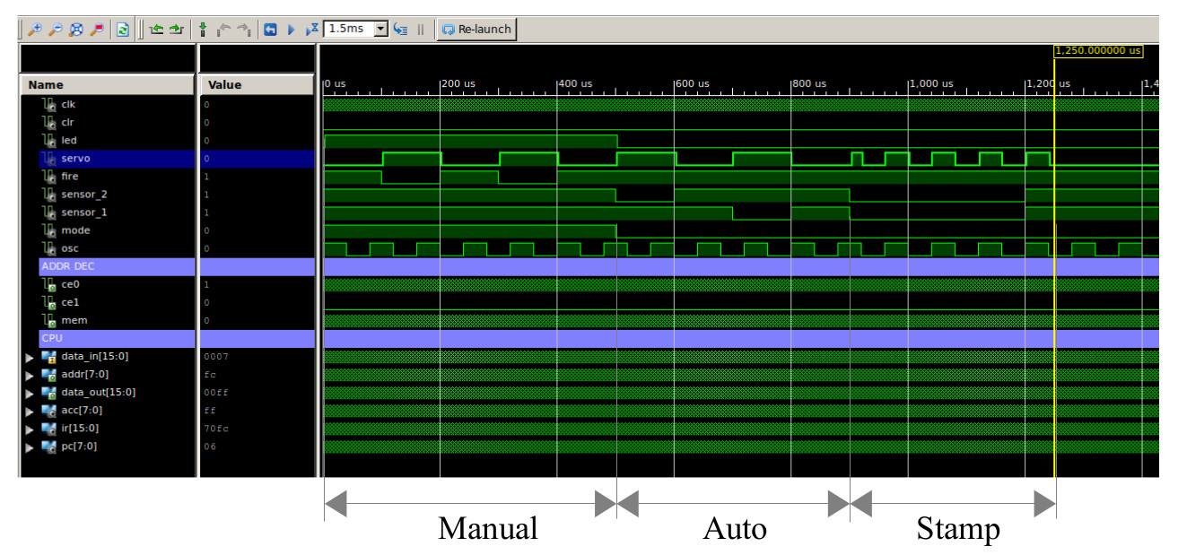
Figure 35 : computer controlled bug trap simulation
A further improvement to this system is the development of a high level, application specific language i.e. a set of high level instructions designed for bug trap related applications. This can be implemented in a number of different ways, however, to simplify software development the M4 pre-processor was used (Link), allowing blocks of assembly code to be replaced with a single high level instruction, as shown below:
define(GPIO, `0xFC')

define(goto, `jumpu $1')

define(turnOnLED, `load eval(GPIO+1)
and 0xFD
add 2
store GPIO')

define(turnOffLED, `load eval(GPIO+1)
and 0xFD
store GPIO')

define(closeTrap, `load eval(GPIO+1)
and 0xFE
add 1
store GPIO')

define(openTrap, `load eval(GPIO+1)
and 0xFE
store GPIO')

define(buttonPressed, `load GPIO
and 0x01
jumpz $1')
Using these macros an assembly code implementation can now be re-implemented using macros, as shown below:
DESCRIPTION             ASSEMBLY CODE               MACRO IMPLEMENTATION
-----------             -------------               --------------------

IF (FIRE)               start:                      start:
THEN                        load 0xFC                   buttonPressed fire
  TURN ON LED               and 0x01
  CLOSE TRAP                jumpz fire              reset:
ELSE                                                    turnOffLED
  TURN OFF LED          reset:                          openTrap
  OPEN TRAP                 move 0x03                   goto start
ENDIF                       store 0xFC
                            jumpu start             fire:
                                                        turnOnLED
                        fire:                           closeTrap
                            move 0x00                   goto start
                            store 0xFC
                            jumpu start
In addition to these simple macros, more complex behaviours can also be implemented e.g. stamp on bug, as shown in the macro below. The variables LOW_COUNT and HIGH_COUNT are assigned fixed addressing within the M4 macro script. This delay function will be called within the stampOnBug macro twice, therefore, it is passed the Ids “1” and “2” to ensure unique label names. The lonDelay macro is called 10 times using the LOOP_COUNT variable to produce the 0.75 second delay. Trap controlled by the openTrap and closeTrap macros.
define(LOW_COUNT, `0xE0')
define(HIGH_COUNT, `0xE1')
define(LOOP_COUNT, `0xE2')

define(longDelay, `move 0
store LOW_COUNT
store HIGH_COUNT
innerLoop$1:
load LOW_COUNT
add 1
store LOW_COUNT
jumpnz innerLoop$1
outerLoop$1:
load HIGH_COUNT
add 1
store HIGH_COUNT
jumpnz innerLoop$1'
)

define(stampOnBug, `closeTrap
move 10
store LOOP_COUNT
closedWait:
longDelay( 1 )
load LOOP_COUNT
sub 1
store LOOP_COUNT
jumpnz closedWait
openTrap
move 10
store LOOP_COUNT
openWait:
longDelay( 2 )
load LOOP_COUNT
sub 1
store LOOP_COUNT
jumpnz openWait'
)

This work is licensed under a Creative Commons Attribution-NonCommercial-NoDerivatives 4.0 International License.
Contact email: mike@simplecpudesign.com