To play a video game we need a game controller, a means of controlling our space ship, or bat :).
Figure 1 : serial port
The first game controller implemented was the existing serial port, to send ASCII characters to the FPGA from the keyboard i.e. WASD, W=Up, D=Fire and S=Down. This is fine for testing and is a useful tool for debugging i.e. allows you to print debug messages, variable values to the screen etc, but to develop a standalone SimpleCPU based games console we need some sort of game pad \ controller. Short video of this controller being used with the Pong game is available here: (Link).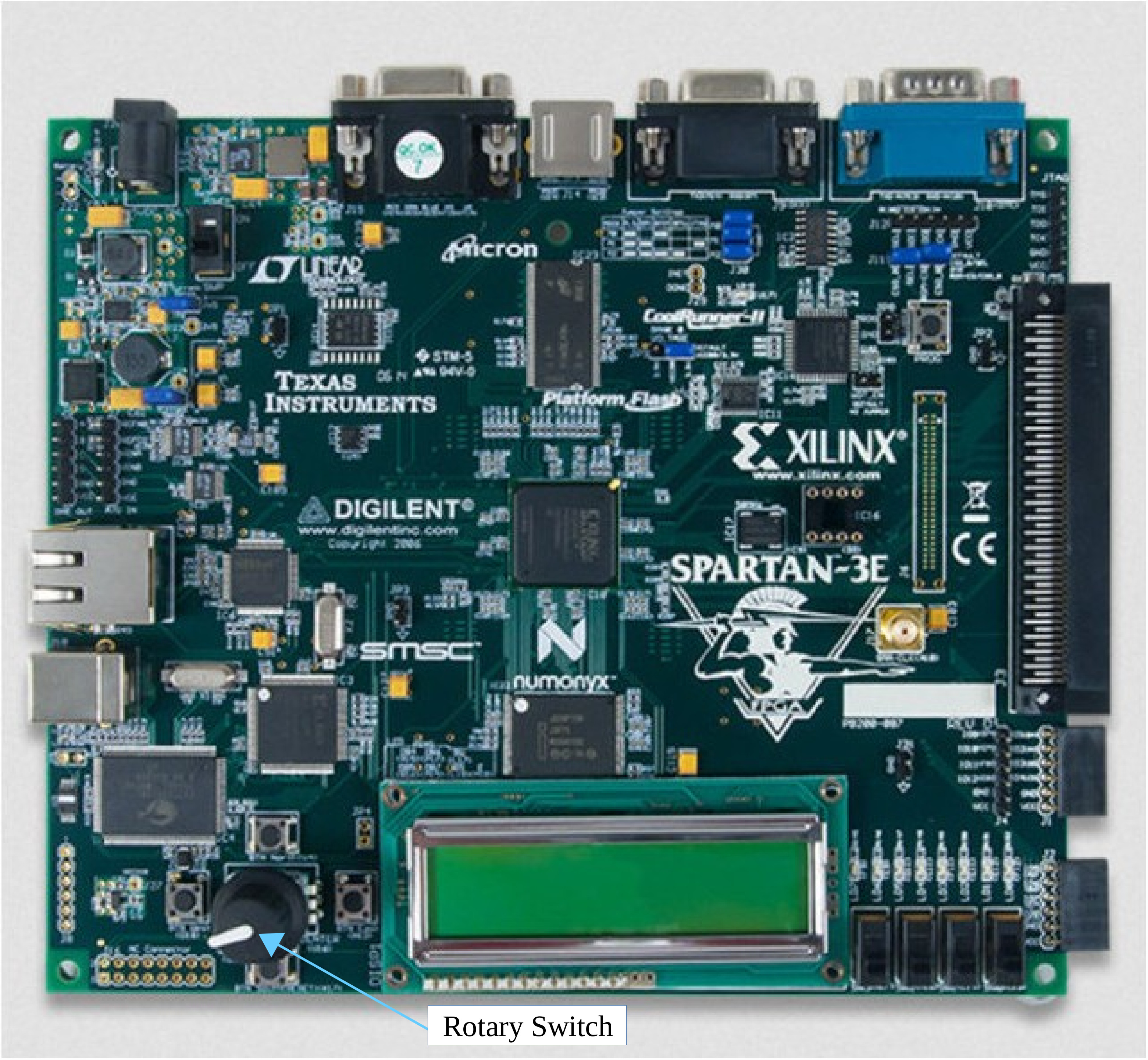
Figure 2 : FPGA Board
One of the FPGA boards used to prototype the VGA controller has a rotary switch, as shown in figure 2. This input hardware is very similar to the hardware used in one of the controllers used in the Atari 2600 i.e. the Driving Controller. The Atari 2600 (Link) is the mother of all video game consoles, and for its age come with a surprisingly wide range of different controllers, as shown in figure 3.
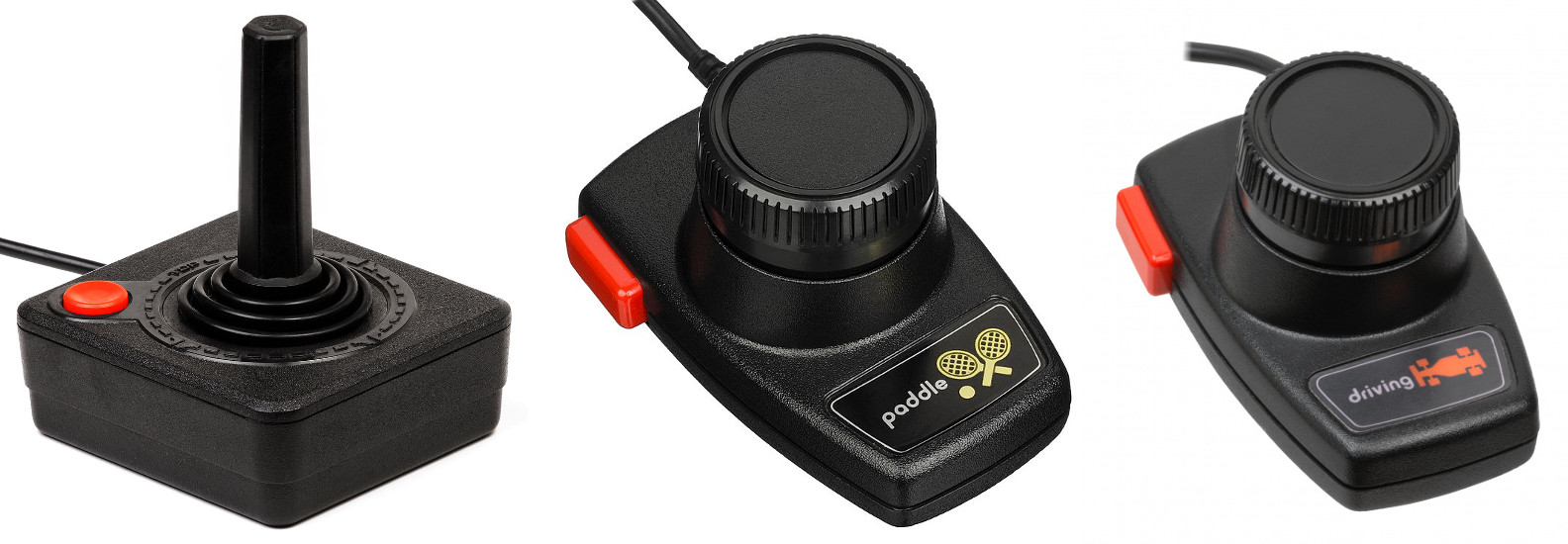
Figure 3 : game controllers, joystick (left), paddle (middle), driving (right)
There were actually a couple more controllers in the Atari catalogue, i believe there was also a small keypad and a game pad. Looking at the controllers in figure 3, its may look like that the paddle and driving controllers are the same i.e. rotary position controllers. However, the paddle is analogue (continuous) and the joystick and driving controllers are digital (discrete). To help in this discussion consider the circuit diagrams of the Atari 2600 shown in figure 4.
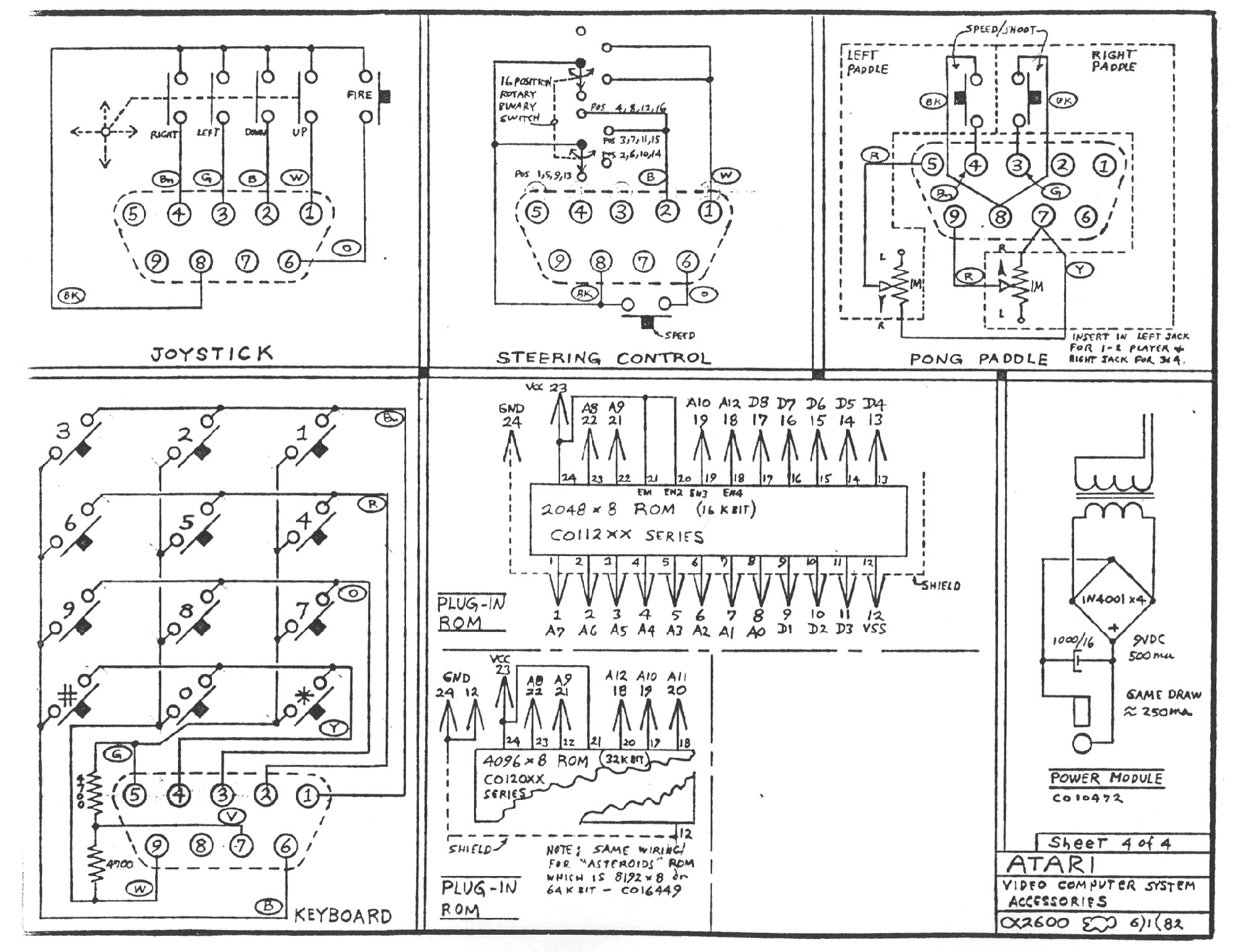

Figure 4 : Atari 2600 schematics, interface (top), main board (bottom)
The pong paddle is implemented using a variable resister (top right schematic), producing an analogue voltage proportional to position i.e. on pins 5 and 9 (left and right 9-way D-connectors), for player 1 and player 2. Therefore, the paddle controller's rotational range is approximately 260 degrees, the rotational range of a typical variable resistor. These analogue signals are processed by the TIA chip (TV Interface Adaptor). This IC must have some sort of analogue to digital converter (ADC). Not sure how this was implemented, documentation for this IC is a little hard to find. However, knowing that the TIAs screen resolution was 160 x 192 pixels, the ADC resolution was probably less that 8bits i.e. the number of pixel positions that need to be represented: 8bits=256, 7bits=128, 6bits=64, 5bits=32. For a simple game like Pong, 5bits is probably sufficient, owing to its limited movement range. The joystick and driving controllers are implemented using switches. The joystick uses simple push-to-make switches (top left schematic), whilst the driving controller uses a rotary switch (top middle schematic). Therefore, the driving controller does not have rotational stop\limit i.e. you can keep rotating the dial forever. The rotary switch on the FPGA board is described in this document (Link) and shown in figure 5.
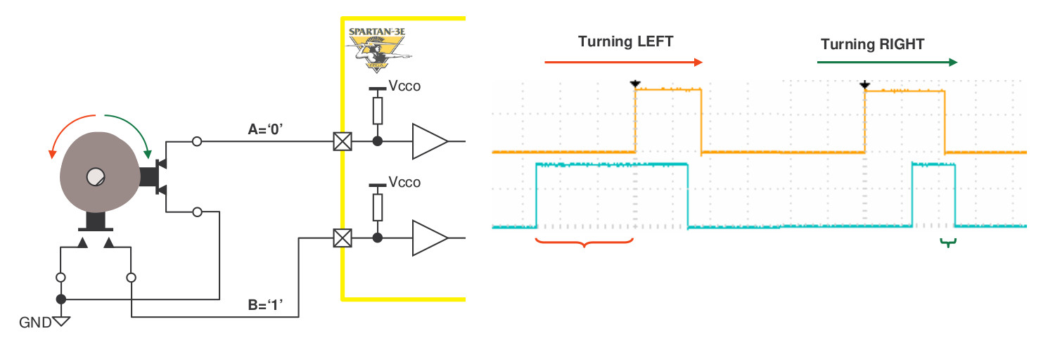
Figure 5 : rotary switch
The rotary switch has two switches: A and B. When rotated anti-clockwise i.e. to the left, the cam\teeth attached to the drive shaft closes switch B first then switch A. When rotated clockwise i.e. to the right, the cam\teeth attached to the drive shaft closes switch A first then switch B. Therefore, by detecting which switch closes first the hardware can determine direction, and by counting the number of pulses generated by these switch it can calculate rotation\distance. The hardware to process these signals (VHDL) is shown in figure 6 (taken from the Xilinx documentation). Note, i do like the switch debounce hardware used.
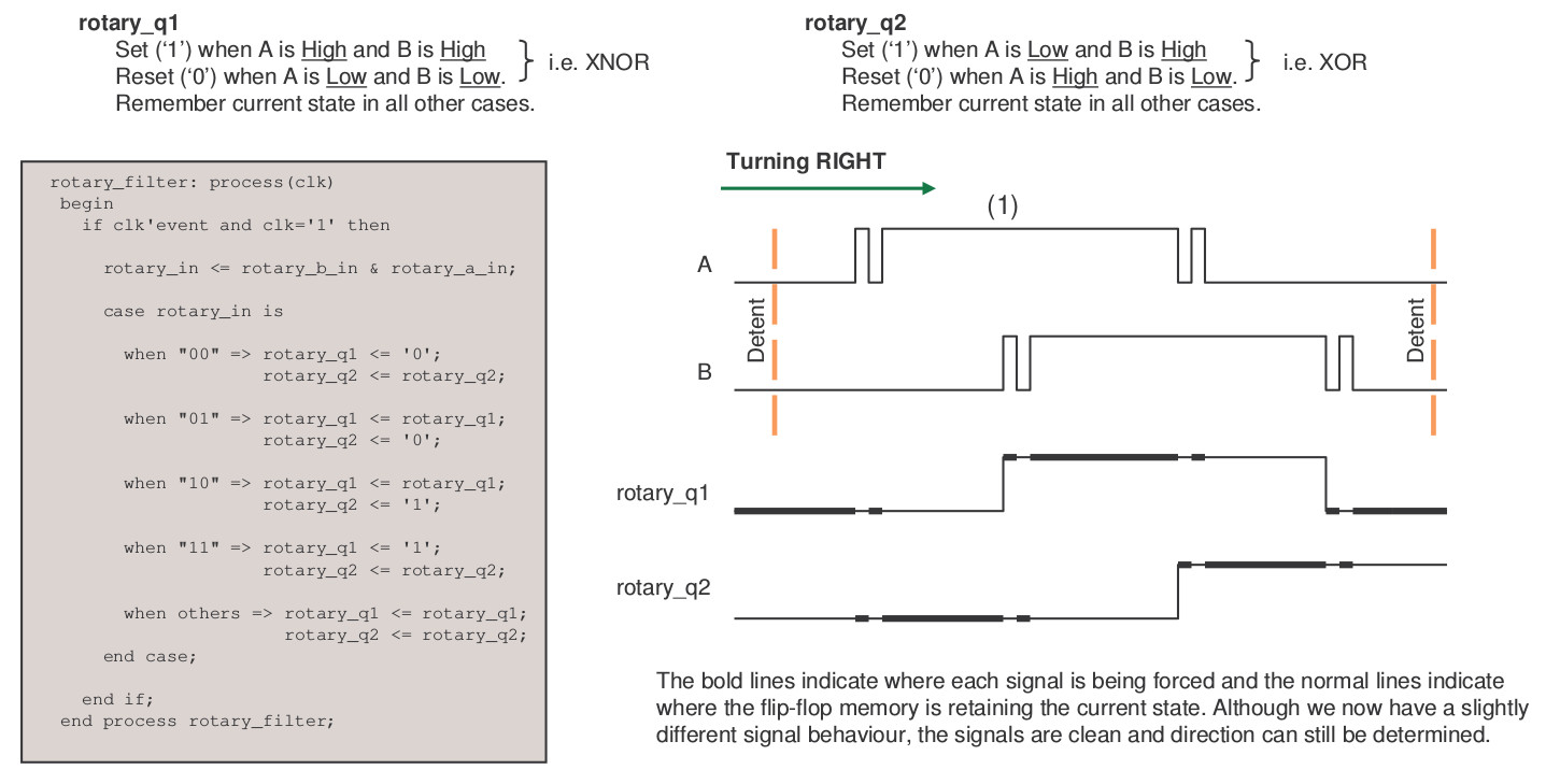
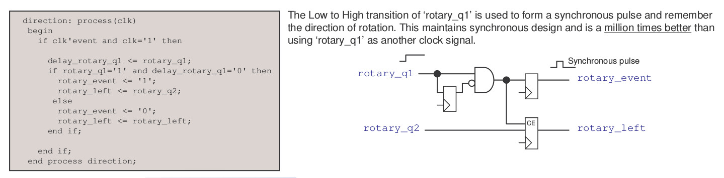
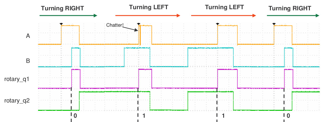
Figure 6 : rotary switch hardware
Using these designs a schematic component can be created allowing the simpleCPU to interface to the rotary switch, as shown in figure 7. The VHDL used to implement the left_right_leds component is shown below (taken from Xilinx reference doc), providing the outputs sw_event and sw_direction. It also provides the sw_pressed signal which is a third switch, triggered when you push down on the rotary switch, rather than rotating it (this will be the Fire button). As the rotary switch's state is polled it is only read once per main loop iteration, therefore, the sw_event signal is used to trigger a SR flip-flop, constructed from a D-type flip-flop. This ensures small position changes are not missed. The state of the push switch is not latched as it is assumed this will be held down for a longer period of time. This SR flip-flop is reset when the processor reads the state of the switch. Note, on reflection the SR flip-flop is not really needed as the main loop iteration time is relatively quick.
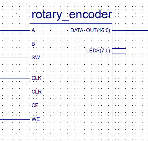
Figure 7 : rotary switch schematic
library IEEE;
use IEEE.STD_LOGIC_1164.ALL;
use IEEE.STD_LOGIC_ARITH.ALL;
use IEEE.STD_LOGIC_UNSIGNED.ALL;

entity left_right_leds is
Port (
   clk             : in std_logic;
   clr             : in std_logic;

   rotary_a       : in std_logic;
   rotary_b       : in std_logic;
   rotary_press    : in std_logic;

   sw_event         : out std_logic;
   sw_direction   : out std_logic;
   sw_pressed     : out std_logic;

   led             : out std_logic_vector(7 downto 0) );
end left_right_leds;


architecture Behavioral of left_right_leds is

    signal      rotary_a_in : std_logic;
    signal      rotary_b_in : std_logic;
    signal  rotary_press_in : std_logic;
    signal        rotary_in : std_logic_vector(1 downto 0);
    signal        rotary_q1 : std_logic;
    signal        rotary_q2 : std_logic;
    signal  delay_rotary_q1 : std_logic;
    signal     rotary_event : std_logic;
    signal      rotary_left : std_logic;

    signal      led_pattern : std_logic_vector(7 downto 0):= "00010000"; --initial value puts one LED on near the middle.
    signal        led_drive : std_logic_vector(7 downto 0);

begin

  rotary_filter: process(clk, clr)
  begin
    if clr='1'
   then
      rotary_a_in     <= '0';
      rotary_b_in     <= '0';
      rotary_press_in <= '0';
      sw_pressed      <= '0';
      rotary_q1       <= '0';
      rotary_q2       <= '0';

    elsif clk'event and clk='1'
   then

      --Synchronise inputs to clock domain using flip-flops in input/output blocks.
      rotary_a_in     <= rotary_a;
      rotary_b_in     <= rotary_b;
      rotary_press_in <= rotary_press;
      sw_pressed      <= rotary_press;

      --concatinate rotary input signals to form vector for case construct.
      rotary_in <= rotary_b_in & rotary_a_in;

      case rotary_in is

        when "00" =>   rotary_q1 <= '0';
                       rotary_q2 <= rotary_q2;

        when "01" =>   rotary_q1 <= rotary_q1;
                       rotary_q2 <= '0';

        when "10" =>   rotary_q1 <= rotary_q1;
                       rotary_q2 <= '1';

        when "11" =>   rotary_q1 <= '1';
                       rotary_q2 <= rotary_q2;

        when others => rotary_q1 <= rotary_q1;
                       rotary_q2 <= rotary_q2;
      end case;

    end if;
  end process rotary_filter;

  direction: process(clk, clr)
  begin
    if clr='1'
    then
      delay_rotary_q1 <= '0';
      rotary_event    <= '0';
      rotary_left     <= '0';
      sw_event        <= '0';
      sw_direction    <= '0';

    elsif clk'event and clk='1'
    then

      delay_rotary_q1 <= rotary_q1;

      if rotary_q1='1' and delay_rotary_q1='0'
      then
        rotary_event <= '1';
        rotary_left <= rotary_q2;
        sw_event <= '1';
        sw_direction <= rotary_q2;
       else
        rotary_event <= '0';
        rotary_left <= rotary_left;
        sw_event <= '0';
        sw_direction <= rotary_left;
      end if;

    end if;
  end process direction;


  led_display: process(clk, clr)
  begin
    if clr='1'
    then
      led_pattern <= "00010000";
      led_drive   <= "00010000";

    elsif clk'event and clk='1' then

      if rotary_event='1' then
        if rotary_left='1' then
          led_pattern <= led_pattern(6 downto 0) & led_pattern(7); --rotate LEDs to left
         else
          led_pattern <= led_pattern(0) & led_pattern(7 downto 1); --rotate LEDs to right
        end if;
      end if;

      if rotary_press_in='0' then
        led_drive <= led_pattern;
       else
        led_drive <= led_pattern xor "11111111";
      end if;

      --Ouput LED drive to the pins making use of the output flip-flops in input/output blocks.
      led <= led_drive;

    end if;
  end process led_display;

end Behavioral;
Short video of this controller being used with the Pong game is available here: (Link).
To make the game console more flexible i.e. not limited to FPGA boards with rotary switches, i needed a generally available games controller. Therefore, Googling for an off the shelf solution, a pre-made unit that doesn't cost tooo much, resulted in a lot of PC based controllers that use an USB interface. Designing the interface hardware for these i'm guessing will be tooo much fun, but watching so Youtube videos on the USB protocol i don't think it would be impossible. An alternative is to use retro gaming console controllers. Reading around the SNES controller's hardware looked simple and they only cost £ 5 :), shown in figure 8.
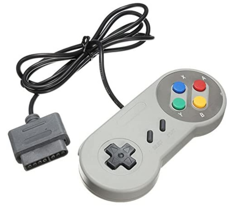
Figure 8 : SNES controller
This controller supports 12 switches and communicates using a serial protocol. Googling around on the web the protocol seems to be as shown in figure 9. Also found some discussion here: (Link). The online resources say that the SNES controller uses +5V, which reflects the voltages used in the 6502 based hardware the SNES was based on. However, the FPGA and most modern hardware uses +3.3V. Solutions, could uses a level shifter to convert the 3.3V outputs up to +5V, and the +5V input down to +3.3V, but as the ICs used in this replica controller work at +3.3V we can simply power the controller from +3.3V and remove the issue.
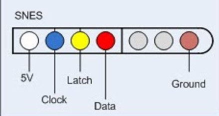
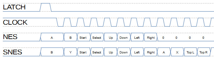
Figure 9 : SNES plug (top), protocol (bottom)
The protocol initially latches\captures button data by pulsing the latch input, then each data bit is shifted out on a falling clock edge. The hardware used to interface to this controller is shown below.
-- =============================================================================================================
-- *
-- * Copyright (c) Mike
-- *
-- * File Name: snes_controller.vhd
-- *
-- * Version: V1.0
-- *
-- * Release Date:
-- *
-- * Author(s): M.Freeman
-- *
-- * Description: SNES controller interface
-- *
-- * Conditions of Use: THIS CODE IS COPYRIGHT AND IS SUPPLIED "AS IS" WITHOUT WARRANTY OF ANY KIND, INCLUDING,
-- *                    BUT NOT LIMITED TO, ANY IMPLIED WARRANTY OF MERCHANTABILITY AND FITNESS FOR A
-- *                    PARTICULAR PURPOSE.
-- *
-- * Notes:
-- *
-- =============================================================================================================

library IEEE;
use IEEE.STD_LOGIC_1164.ALL;
use ieee.std_logic_arith.all;
use ieee.std_logic_unsigned.all;

entity snes_controller is
Port (
    clk          : in  STD_LOGIC;
    clr          : in  STD_LOGIC;
    addr         : in  STD_LOGIC;
    data_in      : in  STD_LOGIC_VECTOR (15 downto 0);
    data_out     : out STD_LOGIC_VECTOR (15 downto 0);
    ce           : in  STD_LOGIC;
    we           : in  STD_LOGIC;
    snes_latch_o : out STD_LOGIC;
    snes_clk_o   : out STD_LOGIC;
    snes_data_in : in  STD_LOGIC);
end snes_controller;

architecture snes_controller_arch of snes_controller is

  TYPE state_type IS (SA0, SA1, SA2, SA3, SA4, SA5);
  SIGNAL present_state, next_state : state_type;

  SIGNAL data_packet : STD_LOGIC_VECTOR (11 downto 0);
  SIGNAL data_ce     : STD_LOGIC;
  SIGNAL data_rst    : STD_LOGIC;

  SIGNAL delay_count     : STD_LOGIC_VECTOR (5 downto 0);
  SIGNAL delay_count_tc  : STD_LOGIC;
  SIGNAL delay_count_rst : STD_LOGIC;
  SIGNAL delay_count_ce : STD_LOGIC;

  SIGNAL bit_count     : STD_LOGIC_VECTOR (3 downto 0);
  SIGNAL bit_count_tc  : STD_LOGIC;
  SIGNAL bit_count_rst : STD_LOGIC;
  SIGNAL bit_count_ce  : STD_LOGIC;

  SIGNAL busy : STD_LOGIC;

begin

  data_out_bus_mux : PROCESS( addr, busy, data_packet )
  BEGIN
    if addr='0'
    then
      data_out <= "000000000000000" & busy;
    else
      data_out <= "0000" & data_packet;
    end if;
  END PROCESS;

  shift_register : PROCESS ( clk, clr )
  BEGIN
    if clr='1'
    then
      data_packet <= (others => '0');
    elsif clk='1' and clk'event
    then
      if data_ce='1'
      then
        if data_rst='1'
        then
          data_packet <= (others => '0');
        else
          data_packet <= data_packet(10 downto 0) & snes_data_in;
        end if;
      end if;
    end if;
  END PROCESS;

  delay_counter_sync : PROCESS ( clk, clr )
  BEGIN
    if clr='1'
    then
      delay_count <= (others => '0');
    elsif clk='1' and clk'event
    then
      if delay_count_ce='1'
      then
        if delay_count_rst='1'
        then
          delay_count <= (others => '0');
        else
          delay_count <= delay_count + 1;
        end if;
      end if;
    end if;
  END PROCESS;

  delay_counter_comb : PROCESS ( delay_count )
  BEGIN
    if delay_count = "11111"
    then
      delay_count_tc <= '1';
    else
      delay_count_tc <= '0';
    end if;
  END PROCESS;

  bit_counter_sync : PROCESS ( clk, clr )
  BEGIN
    if clr='1'
    then
      bit_count <= (others => '0');
    elsif clk='1' and clk'event
    then
      if bit_count_ce='1'
      then
        if bit_count_rst='1'
        then
          bit_count <= (others => '0');
        else
          bit_count <= bit_count + 1;
        end if;
      end if;
    end if;
  END PROCESS;

  bit_counter_comb : PROCESS ( bit_count )
  BEGIN
    if bit_count = "1100"
    then
      bit_count_tc <= '1';
    else
      bit_count_tc <= '0';
    end if;
  END PROCESS;

  controller_sync : PROCESS( clk, clr )
  BEGIN
    IF clr='1'
    THEN
      present_state <= SA0;
    ELSIF clk'event and clk='1'
    THEN
      present_state <= next_state;
    END IF;
  END PROCESS;

  controller_comb: PROCESS( present_state, ce, we,
                            delay_count_tc, bit_count_tc,
                            data_ce, data_rst  )
  BEGIN
    snes_latch_o <= '0';
    snes_clk_o   <= '1';

    delay_count_rst <= '1';
    delay_count_ce  <= '1';

    bit_count_rst   <= '1';
    bit_count_ce    <= '1';

    data_rst  <= '0';
    data_ce   <= '0';

    busy      <= '0';

    CASE present_state IS
      WHEN SA0 =>
        if ce='1' and we='1'
        then
          next_state <= SA1;
        else
          next_state <= SA0;
        end if;

      -- LATCH PULSE

      WHEN SA1 =>
        delay_count_rst <= '0';
        delay_count_ce  <= '1';

        bit_count_rst <= '0';
        bit_count_ce  <= '0';

        data_rst  <= '1';
        data_ce   <= '1';

        snes_latch_o <= '1';
        snes_clk_o   <= '1';

        busy <= '1';

        if delay_count_tc='1'
        then
          next_state <= SA2;
        else
          next_state <= SA1;
        end if;

      -- WAIT TO START

      WHEN SA2 =>
        delay_count_rst <= '0';
        delay_count_ce  <= '1';

        bit_count_rst <= '0';
        bit_count_ce  <= '0';

        data_rst  <= '0';
        data_ce   <= '0';

        snes_latch_o <= '0';
        snes_clk_o   <= '1';

        busy <= '1';

        if delay_count_tc='1'
        then
          next_state <= SA3;
        else
          next_state <= SA2;
        end if;

      -- CLK LOW, CAPTURE DATA

      WHEN SA3 =>
        delay_count_rst <= '0';
        delay_count_ce  <= '1';

        bit_count_rst <= '0';
        bit_count_ce  <= '1';

        data_rst  <= '0';
        data_ce   <= '1';

        snes_latch_o <= '0';
        snes_clk_o   <= '0';

        busy <= '1';

        next_state <= SA4;

      -- WAIT CLK LOW

      WHEN SA4 =>
        delay_count_rst <= '0';
        delay_count_ce  <= '1';

        bit_count_rst <= '0';
        bit_count_ce  <= '0';

        data_rst  <= '0';
        data_ce   <= '0';

        snes_latch_o <= '0';
        snes_clk_o   <= '0';

        busy <= '1';

        if delay_count_tc='1'
        then
          next_state <= SA5;
        else
          next_state <= SA4;
        end if;

      -- WAIT CLK HIGH

      WHEN SA5 =>
        delay_count_rst <= '0';
        delay_count_ce  <= '1';

        bit_count_rst <= '0';
        bit_count_ce  <= '0';

        data_rst  <= '0';
        data_ce   <= '0';

        snes_latch_o <= '0';
        snes_clk_o   <= '1';

        busy <= '1';

        if delay_count_tc='1'
        then
          if bit_count_tc='1'
          then
            next_state <= SA0;
          else
            next_state <= SA3;
          end if;
        else
          next_state <= SA5;
        end if;

      WHEN OTHERS =>
        next_state <= SA0;  --default condition

    END CASE;
  END PROCESS;

end snes_controller_arch;
Using this design a schematic component can be created allowing the simpleCPU to interface to the SNES controller, as shown in figure 10.
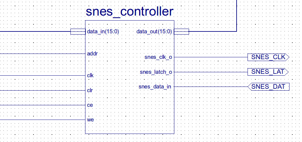
Figure 10 : SNES component
Short video of this controller being used with the Pong game is available here: (Link).

This work is licensed under a Creative Commons Attribution-NonCommercial-NoDerivatives 4.0 International License.
Contact email: mike@simplecpudesign.com