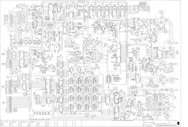
When is a simple cpu not simple enough? Answer: when you are learning to program in assembler :). When i started my journey into computers at school you had one choice: BBC Micro (Link) and Basic (Link). This computer is based on the 6502 (Link), a simple 8bit processor, allowing anyone with a basic understanding of electronics to understand this computer's hardware, shown in figure 1. These were also simpler times with regards to programming languages, typically starting with Basic, but soon progressing to assembler (Link) owing to the performance limitations of the interpreted Basic programming language. As a result students had a shorter path from software to hardware, so had a better low level understanding of how a computer worked.

Figure 1 : BBC computer schematic
Today the distance between software and hardware is huge, software components abstract away from the underlying hardware, separating the user from the processor. As a result students coming to computer science do not have that DIY, low level, electronics experience of old. Also, the programming style used by modern high level programming languages i.e. function / method focused, OO style, is a world removed from low level programming languages such as assembler, where a basic understanding of the underlying hardware is required. As a result students need to relearn how to program, how to breakdown a problem into a sequence of low level, simple instructions, rather than relying on built in functions and libraries. To aid is this transition from a high level language such as python / java, to the simple assembly language used on the SimpleCPU, i designed an assembly like language for a minimalCPU processor.
MinimalCPU v1
Instruction Set Simulator - v1
Instruction Set Simulator - v2

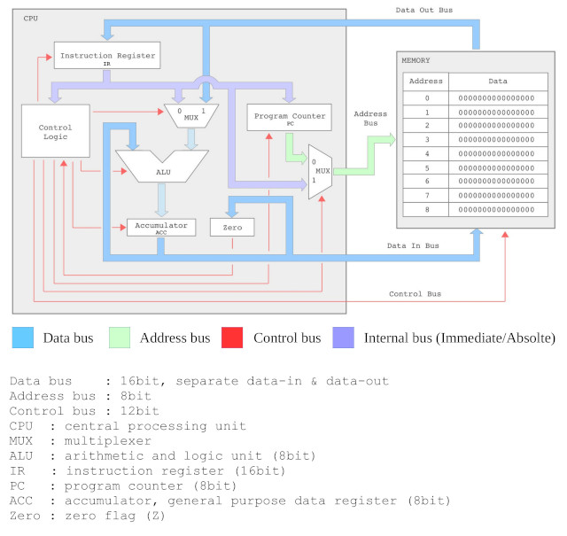
Figure 2 : SimpleCPU version 1
Traditional assembly languages come with the joys of having to know about the hardware, consider the SimpleCPU version 1 shown in figure 2. To understand this block diagram a student needs to understand its architectural building blocks: buses, multiplexers, registers, accumulator etc. This knowledge is needed to understand the function and terminology used by its assembly language instructions. Therefore, the minimal CPU needs to remove this requirement, whilst still using an assembler style syntax, it needs to abstract away from: Busses, Memory and Registers etc. This may seem like fundamental stuff, when considering computer architectures and you would be correct, however, the focus here is develop an architecture, an assembly language that is easy to understand, rather than being one that is easy to implement in hardware. An example program is shown below:
start:
  add A 1
  add B 2
test:
  and A B
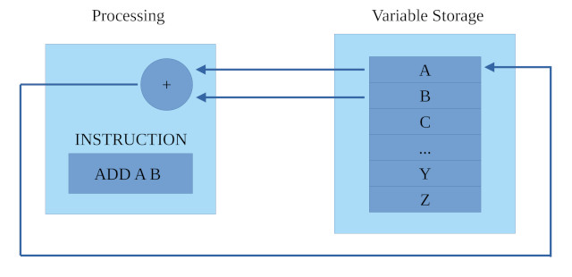
The minimalCPU does not have the concept of an address, rather data is stored in variables, A to Z, so it has 26 data "storage" locations. Therefore, it also has no concept of memory i.e. data or instruction locations, rather its memory is the text file used to store its program, it is a list of instructions that will be sequentially executed, one after another. Positions within this program can be identified by labels i.e. text ending with a ":". In the above example there are two labels start and test. Therefore, from one point of view, you can consider this machine to be comparable to a type of data-flow architecture, as shown in figure 3. With each instruction setting up a data path, from our variables, through a functional block and then back into a variable.

Figure 3 : processing architecture
Instructions can be either one operand or two operand formats. An instruction has an OPCODE that defines its functions and then one or two OPERANDs that define the data that this function will process. To keep things simple the first version of the CPU supports three instructions, using two addressing modes i.e. methods of getting your data, "variables" and "constants" :
INSTRUCTION      DESCRIPTION                               EXAMPLE

AND X Y          Perform the bitwise AND function on       X = X AND Y
                 two variables X and Y, storing the        AND 11011011 00001111
                 result in variable X.
                                                           X = 11011011
                                                           Y = 00001111
                                                               --------
                                                               00001011
                                                               --------

AND X 10         Perform the bitwise AND function on       X = X AND 10
                 variable X and constant 10, storing       AND 11011011 00001010
                 the result in variable X.
                                                           X = 11011011
                                                           Y = 00001010
                                                               --------
                                                               00001010
                                                               --------

ADD X Y          Perform the ADDITION function on          X = X ADD Y
                 two variables X and Y, storing the        ADD 11011011 00001111
                 result in variable X.
                                                           X = 11011011
                                                           Y = 00001111
                                                               --------
                                                               11101010
                                                               --------
                                                                 11111

ADD X 10         Perform the ADDITION function on          X = X ADD Y
                 variable X and constant 10, storing       ADD 11011011 00001010
                 the result in variable X.
                                                           X = 11011011
                                                           Y = 00001010
                                                               --------
                                                               11100101
                                                               --------
                                                                 11 1

JPZ loop         Jump to label "loop" is the last          start:
                 calculation generated a zero result,          AND Z 0
                 this example implementing a loop              JPZ start
The two operand syntax: OPCODE : OPERAND_0 : OPERAND_1. Operand_0 must be a variable as this is used to store the result. Operand_1 can be a variable or a constant. Both variables and constants are 8bit values. Note, i decided to break my rule regarding abstracting away from the hardware here as this allows more interesting quizzz questions later, but for now what this means is that variables and constants are limited to integers within the range 0 to 255. Early quizzz questions limit calculations to results within this range, so all is fine, however, if you do generate a result bigger than 255 the result will loop around back through 0 e.g. 255+1=0, 255+2=1, 255+3=2 ...
The one operand syntax: OPCODE : OPERAND_0, is used by the JUMP instruction, this is a label within the program e.g. in the previous example program if you wanted to jump back to the beginning of program you could execute the instruction : jpz start, where start is a label. Note, this jump is only performed if the pevious calculation produced a zero result i.e. there are no unconditional jumps, exactly the same as the classic first generation computer EDSAC (Link).
Using just these three instructions the first programming task for the students is to answer the questions below. The aim here is force students to consider how to combine these simple instructions, such that they can implement the functionality needed to solve these more complex programming tasks :). You can download a PDF copy of these questions here: (Link).
Q1) the memory locations X and Y are initialised with the values:

                128  64  32  16  8  4  2  1
X = 14   =    	0    0   0   0   1  1  1  0
Y = 35   =   	0    0   1   0   0  0  1  1

Consider the program below, what is the final value stored in memory location X? Hint, remember
that the first variable i.e. X in this example, is overwritten with the result.

ADD X, Y
AND X, Y

Q2) write a program to initialise memory locations X and Y to the following values
X = 123 and Y = 0x123 i.e. load these values into memory.

Hint, you can pass an instruction a hard-coded value e.g. AND X, 67, rather than two variables
e.g. AND X, Y. Also, consider the two scenarios where the original value stored in the memory
location is zero and when it is a non zero value. A number starting with 0x indicates that the
following value is in hexadecimal i.e. base 16, rather than the default base 10.

Q3) write a program to perform the following calculation.

X = X * 5

Hint, what is multiplication? You will need to use multiple instructions to implement this function.

Q4) write a program to perform the following calculation. Your solution must use less than eight
instructions.

X = X * 16

Q5) write a program to perform the following calculation i.e. the multiplication of two unknown
variables.

X = X * Y

Hint, you will need to use the JUMP instruction. Jumps are made to labels within a program i.e.
a name (label) ending with a ":". Consider the example below, the JPZ instruction jumps to the
label START, if the result of the ADD instruction produces a zero result, otherwise the next
instruction in the program is executed i.e. this code gets stuck in an infinite loop.

START:                    START:
   AND X 0                   X=0
   AND Y 0                   Y=0
   ADD X Y                   X=X+Y
   JPZ START                 IF RESULT = 0 THEN START
   ADD Z X                   Z=Z+X

Q6) write a program to perform the following calculation.

X = X OR Y

where the OR function performs a bitwise OR on the memory locations X and Y. Like the bitwise
AND instruction, the bitwise OR instruction will perform the logical OR function on each bit
position. Consider the exmaple below:

OR 11011011 00001111

X = 11011011
Y = 00001111
    --------
    11011111
    --------

Your solution must be less than 16 instructions. You may assume X and Y have already been
loaded into memory. Hint, this one is tricky :)
Don't judge :), this is a cheap and cheerful, command line, instruction set simulator for the minimalCPU, written in everyone's favourite programming language python. The aim here was not to write the fastest simulator, or the most compacted, or to factor out each function, but rather to produce code that was simple to read / understand. Code that an inexperienced programmer could understand and improve. You can download a copy here: (Link). Note, still a work in progress so may have some "features", not fully tested this code in Windows, i only play game in Windows :).
#!/usr/bin/python3 import getopt import sys import os import re import time if sys.platform =='win32': import msvcrt else: import tty import termios ################### # INSTRUCTION-SET # ################### # a very simple instruction set simulator for the minimal cpu, # program file plain text, single step through program. ############# # VERSION 1 # ############# # ADD X Y ADD X 0 # AND X Y AND X 0 # JPZ
To test this simulator i used the simple test program shown below. This program loads X=252 and Y=1. Then enters a while loop, incrementing X, until an overflow occurs, causing the program to finish. Note, the final add x 0 is a NOP i.e. a No Operation instruction. You can download a copy here: (Link).
start:
    and x 0
    and y 0
    add x 252
    add y 1
loop:
    add x y
    jpz exit
    add z 0
    jpz loop
exit:
    add x 0
This simulator is a command line program, therefore, to run this program you will need to open your favourite flavour of command line e.g. for Windows Anaconda (Link), or Linux your normal terminal, as shown in figure 4.

Figure 4 : command line
At the command line you can specify:
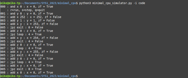
A screen shot of the above program's instruction trace is shown in figure 5. The first three digit number is the line number in the text file of the instruction being executed, starting at line 0. Why 0, well everything starts at 0 in computer science :). ZF=Zero flag, this is set to TRUE if the last calculation produced a zero result.

Figure 5 : instruction trace
The simulator executes the first instruction, the user can choose to single step through the program i.e. execute one instruction at a time, by pressing the S key, or run to completion by pressing the R key. After each instruction is executed the status of the updated variable and ZF are printed to the screen. You can also display the state of all variables by pressing the V key. To finish the program before it is completed press the Q key. Note, if you press the R key and you code get stuck in an infinite loop, CRTL-C is your friend :).
Some small improvements, updates. Added a -s commandline switch, this allows a used to initialise a variable before run time. The parameter format is VARIABLE:VALUE e.g. -s a:123 will initialise the variable 'A' to the value 123, an example is shown in figure 6 below.

Figure 6 : initialising variables
In this example the program file code.asm contains a single instruction ADD X Y. The variables X is set to 10 and Y is set to 30 using the -s switch. To see the final result another small change was made to the code, on completion of the program all variables are printed to the screen i.e. so we can see the result X = 30. You can download a copy here: (Link).
WORK IN PROGRESS

This work is licensed under a Creative Commons Attribution-NonCommercial-NoDerivatives 4.0 International License.
Contact email: mike@simplecpudesign.com