To save space and to simplify the implementation of the hardware used by the various network services it has been constructed in a 1U rack, the key components used to construct this 1U rack are:
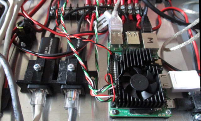
Figure 1: Mail Pi
This node implements a central mail server, allowing different Base nodes in the lab to send emails to each other regarding significant events e.g. errors in lab scripts, extreme temperature readings etc. The mail server software installed on this Pi is the same as that used on the Base node i.e. PostFix (Link) + Dovecot (Link). Postfix is a Mail Transfer Agent (MTA), used to route email messages between hosts and was installed using the command:
sudo apt-get install postfix

CONFIGURATION
-------------
Postfix configuration: Internet Site
Mail name: raspberrypimail.local

ADDITIONAL SOFTWARE
-------------------
sudo apt-get install dovecot-core dovecot-pop3d dovecot-imapd s-nail mailutils mutt
Note, if needed the postfix configuration can be updated using:
sudo dpkg-reconfigure postfix
The configuration file for Postfix is stored in: /etc/postfix/main.cf, a copy of the Mail node's file is shown below:
# See /usr/share/postfix/main.cf.dist for a commented, more complete version

smtpd_banner = $myhostname ESMTP $mail_name (Raspbian)
biff = no

# appending .domain is the MUA's job.
append_dot_mydomain = no

readme_directory = no

# See http://www.postfix.org/COMPATIBILITY_README.html -- default to 2 on
# fresh installs.
compatibility_level = 2

# TLS parameters
smtpd_tls_cert_file=/etc/ssl/certs/ssl-cert-snakeoil.pem
smtpd_tls_key_file=/etc/ssl/private/ssl-cert-snakeoil.key

smtpd_use_tls=no

smtpd_tls_session_cache_database = btree:${data_directory}/smtpd_scache
smtp_tls_session_cache_database = btree:${data_directory}/smtp_scache

smtpd_relay_restrictions = permit_mynetworks permit_sasl_authenticated defer_unauth_destination
myhostname = raspberrypi-mail.local
alias_maps = hash:/etc/aliases
alias_database = hash:/etc/aliases

myorigin = /etc/mailname
mydestination = raspberrypi-mail.local, localhost.local, localhost
relayhost =
mynetworks = 127.0.0.0/8, 192.168.0.0/16

mailbox_size_limit = 0
recipient_delimiter = +

inet_interfaces = all
inet_protocols = ipv4

home_mailbox = Maildir/
mailbox_command =
In addition to Postfix the Mail node also uses Dovecot as its mail storage server i.e. mail is delivered to the server using a Mail Delivery Agent (MDA) and stored for later access via an email client, a Mail User Agent (MUA). The configuration file for Postfix is stored in: /etc/dovecot/dovecot.conf, a copy is shown below:
## Dovecot configuration file

# Enable installed protocols
!include_try /usr/share/dovecot/protocols.d/*.protocol

# A comma separated list of IPs or hosts where to listen in for connections.
# "*" listens in all IPv4 interfaces, "::" listens in all IPv6 interfaces.
# If you want to specify non-default ports or anything more complex,
# edit conf.d/master.conf.
listen = *


##
## Dictionary server settings
##

# Dictionary can be used to store key=value lists. This is used by several
# plugins. The dictionary can be accessed either directly or though a
# dictionary server. The following dict block maps dictionary names to URIs
# when the server is used. These can then be referenced using URIs in format
# "proxy::".

dict {
  #quota = mysql:/etc/dovecot/dovecot-dict-sql.conf.ext
  #expire = sqlite:/etc/dovecot/dovecot-dict-sql.conf.ext
}

# Most of the actual configuration gets included below. The filenames are
# first sorted by their ASCII value and parsed in that order. The 00-prefixes
# in filenames are intended to make it easier to understand the ordering.
!include conf.d/*.conf

# A config file can also tried to be included without giving an error if
# it's not found:
!include_try local.conf

disable_plaintext_auth = no
mail_location = maildir:~/Maildir
To initially create the file structures used to implement each users mailbox the following commands were used (below) to create a default directory structure, this was then copied into each users home directory.
CREATE
------
sudo maildirmake.dovecot /etc/skel/Maildir
sudo maildirmake.dovecot /etc/skel/Maildir/.Drafts
sudo maildirmake.dovecot /etc/skel/Maildir/.Sent
sudo maildirmake.dovecot /etc/skel/Maildir/.Spam
sudo maildirmake.dovecot /etc/skel/Maildir/.Trash
sudo maildirmake.dovecot /etc/skel/Maildir/.Templates

COPY
----
sudo cp -r /etc/skel/Maildir /home/desk-90/
sudo chown -R desk-90:desk-90 /home/desk-90/Maildir/
sudo chmod -R 700 /home/desk-90/Maildir/
This process was repeated for each desk in the lab i.e. accounts were created on the Mail node for users desk-1 to desk-85. As always in these cases this was done using some of my "best" shell script code :). To test that the Postfix service is operating correct you can use the command line tools: telnet or s-nail. Using telnet we can connect to port 25 and send plain text SMTP commands.
TELNET
------
telnet 192.168.100.2 25
helo pc.local
mail from: mike@pc.local
rcpt to: mike@raspberrypi-mail.local
data
Subject: test
hi
test
mike
.
quit
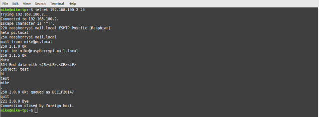
Figure 2: testing an email server using telnet
Alternatively, this process can be automated using s-nail, an example below. Note, the senders email address is stored in /etc/mailname.
echo "this is a test email" | s-nail -s "test" mike@raspberrypi-mail.local
To test that the email was sent to the mail server we can check the log file: /var/log/mail.log (if you have root access on that host). Alternatively, if you only have user access you can examine your Maildir inbox. Each time a mail is received a new file is created in the "new" email directory i.e. /home/USER/Maildir/new. You can use each files time stamp to identify the last email received, then display its contents on the screen using cat or less:

Figure 3: reading emails using cat
Note, the filename will vary from machine to machine. Alternatively, you can also examine the local inbox using the Mutt application. Login to the remote machine (using the correct username i.e. desk-X or pi) and run the command mutt from the terminal. This will launch the Mutt email client, as shown below. Note, not sure why i lost the "from" email field in mutt


Figure 4: reading emails using mutt (to see full headers press 'h')
The Mail node is implemented using a Pi-3b+ and in addition to acting as the lab's mail server it also implements a router, connecting the 172.16.200.0/24 and the 172.16.201.0/24 networks to the 192.168.0.0/16 network. The 192 network is implemented using the Pi-3+'s onboard NIC i.e. ETH0. The 172 networks are implemented using two USB-to-Ethernet adaptors, ETH1 and ETH2, as shown in figures 1 and 5.
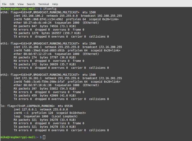
Figure 5: email server NICs
These IP addresses of these NICs are statically defined in /etc/network/interfaces:
auto lo
iface lo inet loopback

auto eth0
iface eth0 inet static
  address 192.168.100.2
  netmask 255.255.0.0

auto eth1
iface eth1 inet static
  address 172.16.200.1
  netmask 255.255.255.0

auto eth2
iface eth2 inet static
  address 172.16.201.1
  netmask 255.255.255.0
To enable forwarding of packets between these interface the following line in the file /etc/sysctl.conf was uncommitted:
net.ipv4.ip_forward = 1
The static routing table for this Pi is shown in figure 6 below i.e. the networks define above. Note, 169.254.0.0/16 networks are for failed DHCP, there is no default gateway set as packets are not allowed to go outside of the lab.

Figure 6: static routing table (no Base nodes connected to the network)
In addition to these static routes the Mail node also uses the Routing Information Protocol (RIP) (Link) to discover other networks that are connected to the lab's network e.g. each Base node's local networks. These will include the renamed loopback interface, and the 172 networks that are specific to each Base node i.e. IP addresses connected to the router, that are based upon its desk number. The RIP protocol is an early example of a protocol that allows hosts to share routing information i.e. broadcast routing tables, as such it does have its limitation and there are better protocols available. However, it is a good starting point to help illustrates the issues / requirements of such protocols i.e. easy to understand and setup. The software used to implement this service is Quagga (Link). When we enable RIP on the Mail and Base nodes the two systems will automatically share their routing tables, as shown in figure 7.
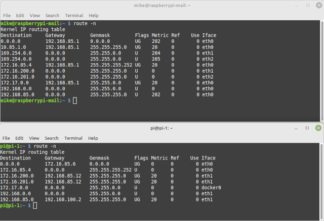
Figure 7: dynamic routing table (Base-90 node connected to the network)
Note, copies of the Quagga conf files can be found in: /usr/share/doc/quagga-core/examples/. For more information on how to setup these conf files refer to (Link).
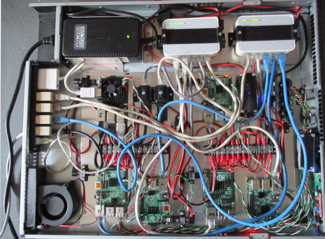
Figure 8: 1U rack
To save space and to make the final implementation more maintainable the Mail, File and Compute nodes and their associated network switches are all housed (and powered) in a 1U rack (Link), as shown in figure 8. Originally this case housed an old server with its associated loud and annoying server grade power supply (high speed fans make sooooo much noise). As this rack is located in my office a quieter machine was needed. Therefore, the normal server power supply was replaced with 5V 8A enclosed power supply i.e. a passively air cooled black-box shown in figure 9. An acrylic back plate was laser cut to match the mains plug position and bolted in place. Aluminium retaining plates were then cut and bent to size to hold the power supply in position, these being pop riveted into the case's steel base. Note, the retaining side plates do not block any ventilation holes i.e. the PSU is a sealed box, also it was hoped that this would help conduct heat into the steel case. The +5V from this PSU is connected to two screw terminal distribution blocks via a 6A fuse. Each Raspberry Pi is powered from these blocks through a 3.2mm DC power-jack to micro-USB adaptor, allowing proper "power" cabling, rather than the cheap and nasty cable you get in a typical micro-USB cables. The two switches require a +9V supply, this is sourced from the +5V supply via a boost converter.
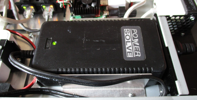
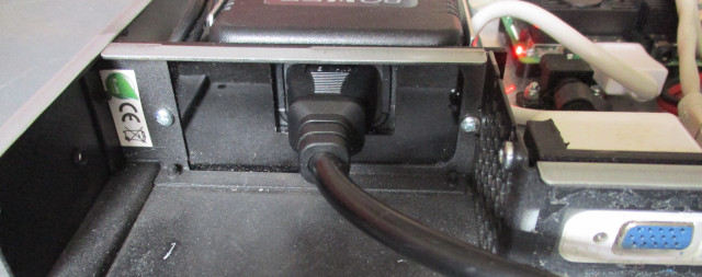
Figure 9 : Power supply
Initially i had hoped that no forced air cooling would be needed i.e. fans, as i thought that the case's top and bottom steel plates would act as reasonable heat sink. That combined with the low power requirements of the switches and Raspberry Pis used in this system, i hoped things would not get tooo hot :). Soak tests backed up the assumptions regarding power supply cooling, this reaching a maximum temperature of 40 °C, shown in figure 10. Note, the recorded temperature is not the working temperature of the electronics within the PSU, rather an indicator to its operating state, this temperature was later reduced with the addition of a back fan. However, this proved not to be the case for some of the Raspberry Pi :(.
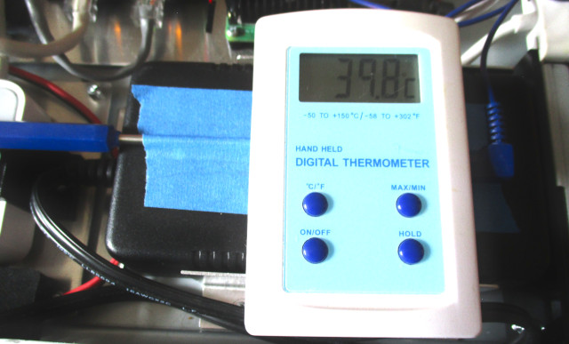
Figure 10 : Power supply cooling (40°C)
A mix of Pi-1, Pi-2 and Pi-3 are used in the implementation of the various nodes in this case. Passive air cooling using small heatsinks proved successful for most of the Raspberry Pis, however, not for the Mail node mounted next to the PSU. This Pi kept rebooting once it reached its "working" temperature. Typically a Raspberry Pi's working temperature is assumed to be -40°C to +85°C, with other components rated from 0°C to +70°C. To monitor each Raspberry Pi's temperature an SSH terminal was opened on each Pi and the following Bash script executed to display the CPU's core temperature:
#!/bin/sh
while true
do
  vcgencmd measure_temp
  sleep 10
done
The system was then left on soak for 2 hours, the working (resting) temperature of each Raspberry Pis still connected to the SSH terminal could then be observed. Raspberry Pis experiencing excessive temperatures could be detected by their disconnected SSH sessions :(. From these experiments the Pi-1 and Pi-2 nodes used to implement the different Compute nodes were found to be operating within their specified temperature ranges. However, the Pi-3 node implementing the Mail node repeatedly crashed and was observed to have reached temperatures above +75°C before rebooting. The working assumption for why this was occurring was owing to its proximity to the PSU, resulting in this Raspberry Pi's heatsinks being unable to passively cool the CPU to a safe working level. To improve cooling a larger heatsink and fan was fitted to this Pi-3, shown in figure 11. The original heatsinks used on Pi-1 and Pi-2 are shown in figure 12.
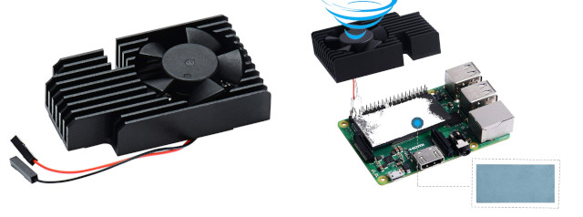
Figure 11 : Pi-3 heatsink
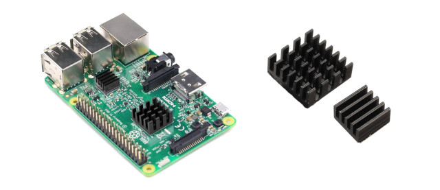
Figure 12 : Pi-1 & Pi-2 heatsink
These heatsinks are attached to the Pi using double sided thermal tape, which i confess i was sceptical about owing to its thickness. Typically, when mounting a heatsink you would use a very thin layer of thermal paste (Link) to maximise the thermal conductivity between the CPU and the heat sink, any gaps or misalignment reducing the ability of the heatsink to move heat away from the CPU. However, this tape does work surprisingly well, allowing the Pi-3 to now operate at +45°C with the fan off and +35°C with the fan on. Note, as these heatsinks are electrical conductive i.e. made from aluminium, and sits above surface-mounted components that have live contacts, i covered the entire under surfaces of these heatsinks with thermal tape to act as an insulator i.e. just in case they slipped, moved out of place. Note, switched the heatsink fan to +3V as +5V was toooo whinny, should make a diode dropper and run off +5V at some point.
With this improvement to the Mail node the system was again soak tested for 24 hours and all nodes proved to be capable of working between +35°C to +45°C. However, to ensure that the system can safely operate under heavier loads / a range of environmental conditions, a rear fan was also added to the case. Note, in reality this system will not be doing any heavy lifting, so overheating should not be an issue. The fan used is a blower style fan, sucking in air from the top of the case and exhausting it out of the rear grill. The ducting connecting the blower to the rear grill is a simple 3D printed box, shown in figure 13, not the ideal shape, but it does isolate / direct the airflow. Note, the space between the fan intake and the cases lid is approximately 8mm, i would of liked this gap to have been larger, but the fan does still move a reasonable amount of air, promoting airflow through the case i.e. intake from front air vents and out the back. Also, it is sucking in air from the top of the case, so that should be the hottest.
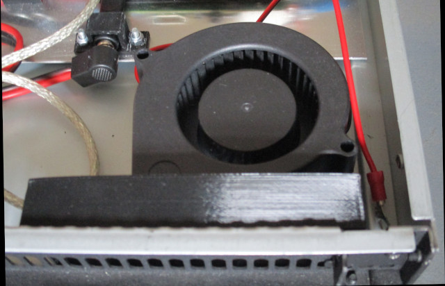
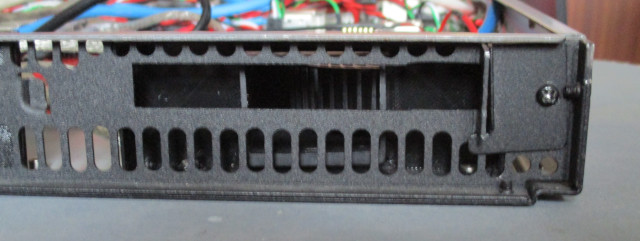
Figure 13 : PSU fan
The hardware in this rack implements a number of the processing nodes and network elements. The position of these Raspberry Pis and network switches within the case is shown in figure 14. Note, the rear panel has a VGA and USB connector allowing the Mail node to be connected to a monitor, keyboard and mouse. There are four network ports on this back panel, allowing connection to the 192.168.0.0/16, 172.16.200.0/24 (x2) and 172.16.201.0/24 networks.
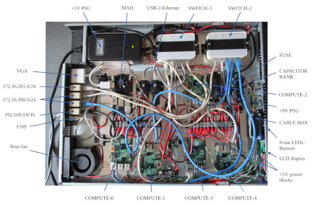
Figure 14 : Rack layout
In addition to the mail server the other core component of the 1U rack is a file server. This is implemented on compute-node-0 a Raspberry Pi-2 shown in figure 14. Note, the eagle eyed people will have spotted that the the 16GB x 2 USB thumb drives are not present at the moment, this is because the ones i was going to use are toooo long and i can't plug them in :(. Therefore, i will have to either cut off the plastic cases, or buy some shorter ones :). This file server uses the File Transfer Protocol (FTP) and the Secure File Transfer Protocol (SFTP). For more information on there protocols refer to: FTP, SFTP.
There are a number of different FTP servers that could be installed, however, the flavor of the moment seems to be vsftpd Link, so to keep things simple thats what i used and was installed using the command:
sudo apt-get install vsftpd
The configuration file for vsftpd is stored in: /etc/vsftpd.conf, a copy of the File node's file is shown below:
# Example config file /etc/vsftpd.conf
#
listen=NO
listen_ipv6=YES
#
# Allow anonymous FTP? (Disabled by default).
anonymous_enable=NO
#
# Uncomment this to allow local users to log in.
local_enable=YES
#
# Uncomment this to enable any form of FTP write command.
write_enable=YES
#
# Default umask for local users is 077. You may wish to change this to 022,
local_umask=022
#
# Activate directory messages - messages given to remote users when they go into a certain directory.
dirmessage_enable=YES
#
# If enabled, vsftpd will display directory listings with the time in  your  local  time  zone.
# The default is to display GMT. The times returned by the MDTM FTP command are also affected by this option.
use_localtime=YES
#
# Activate logging of uploads/downloads.
xferlog_enable=YES
#
# Make sure PORT transfer connections originate from port 20 (ftp-data).
connect_from_port_20=YES
#
# You may fully customise the login banner string:
ftpd_banner=Welcome to Bob's FTP service.
#
# You may restrict local users to their home directories.  See the FAQ for the possible risks in this before
# using chroot_local_user or chroot_list_enable below.
chroot_local_user=YES
#
# This option should be the name of a directory which is empty.  Also, the directory should not be writable
# by the ftp user. This directory is used as a secure chroot() jail at times vsftpd does not require filesystem
# access.
secure_chroot_dir=/var/run/vsftpd/empty
#
# This string is the name of the PAM service vsftpd will use.
pam_service_name=vsftpd
#
# This option specifies the location of the RSA certificate to use for SSL encrypted connections.
rsa_cert_file=/etc/ssl/certs/ssl-cert-snakeoil.pem
rsa_private_key_file=/etc/ssl/private/ssl-cert-snakeoil.key
ssl_enable=NO

# set FTP path to USER directory
user_sub_token=$USER
local_root=/home/$USER/ftp/files
Then to stop the FTP server getting upset and give you a 500 error message you need to make to make the ftp root directory none writable, confess forgot why :).
sudo chmod a-w /home/$USER/ftp/files
WORK IN PROGRESS

This work is licensed under a Creative Commons Attribution-NonCommercial-NoDerivatives 4.0 International License.
Contact email: mike@simplecpudesign.com