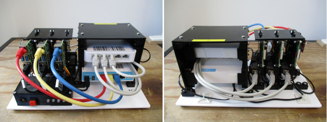

Figure 1 : Raspberry Pi base system, front (left), back (right), power supply (bottom)
The purpose of the Base node is to allow students to explore different network configurations and the different network protocols used on them i.e. the students have full admin control of these systems, allowing them to construct different network scenarios, what can go wrong :). Therefore, owing to security “concerns” the Raspberry Pis in the Base node (shown in figure 1) are not allowed direct Internet access :(. Which for a project that is entitled "Networking" may seem like a bit of deal breaker. However, for me, you don't necessarily need access to the Internet when teaching networking, you just need some hosts and a shared communications network, however, it would have been nice to have Internet access :).
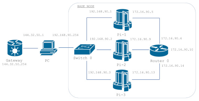
Figure 2 : Raspberry Pi base system network for DESK-90
Note, the network people looking at figure 2 will be shouting "you fool you have used a supercomputer icon to represent the Pi", however, that was deliberate, the icon's shape represents the classic Cray-1 supercomputer (Link), i always thought when viewed from above it looks like a pie chart, so the section being pulled out looks like a piece of Pi, maybe a slice of Raspberry Pi :)
The IP addresses within the Base node start with 192 and 172 i.e. they are private networks, not Internet routable, and are linked to the desk number used in the lab. In the example shown in figure 2, the desk number is 90, therefore, the IP addresses for Pi-1 are 192.168.90.1 and 172.16.90.5, allowing each Base node to be assigned an unique address on the lab's internal network. Note, the lab has 85 desks, numbered 1 to 85, desk 90 was selected for the demo system.
The internal network used by each Base node is divided up into four separate subnets:
The /30 network interfaces connecting each Pi to the Router can be used to join two base systems together, to create scenario specific network connections between selected Raspberry Pis i.e. using specific routing rules within the router. Thats when the fun starts :).
Each Raspberry Pi within the Base node is configured to run Quagga (Link), a network routing software suite, supporting RIP, OSPF and BGP. Forwarding is enabled between the Pis network interfaces, allowing each Raspberry Pi to be a host and a router on its network connections. Each Pi has two physical network interfaces i.e. ETH0 (onboard NIC) and ETH1 (USB-to-Ethernet adapter). Each Pi also has a renamed loopback interface lo:1 to enable more “interesting” routing problems. The WIFI interface on each Pi is not enabled owing to concerns that these would interfere with the department's WIFI network :(. A typical NIC configuration is shown in figure 3, in this example for desk 90.
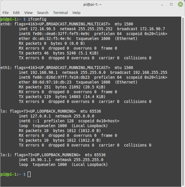
Figure 3 : Base node, Raspberry Pi-1 network interface configuration
Note, the renamed loopback interface lo:1 was added to each Pi to provide a network interface that was not visible from the outside i.e. an "internal" interface, by default this interface is only visible to that host. Therefore, to remotely access services running on this interface, manual routing rules will need to be added to each host, or routing protocols setup to make these internal interfaces visible to external hosts.
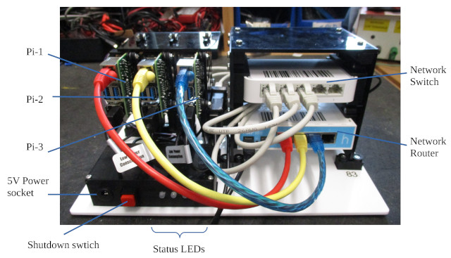

Figure 4 : Base node, router and switch.
The Raspberry Pis used in the Base node are Pi4s, allowing Gigabit networking, however, to save money the switch and the router are only 100Mb :(. The switch is a TP-Link model TL-SF1005D 100/100Mbs desktop switch. The router is a MikroTik hAP Lite Classic Router - RB941-2nD (RouterOS L4), as shown in figure 4.
The power for each Pi, switch and router is supplied from a single 5A +5V power supply, perhaps a little underrated for what we are running, but seems to work OK i.e. we are not pushing large amounts of processing or network traffic through this system, so these hardware elements will not be pulling their stated MAX power. However, every now and again we do get a low power warnings on the Pi, but thats fine :). Power to each Pi could have been routed through the GPIO header i.e. the +5V GPIO pins, however, i strongly disagree with this way of powering a Pi. Yes, it does work, but bypassing the input power filters and polyfuse is never a good idea. In the event of something bad happening on a Pi you would get the PSUs full power flowing through that problem, which is bad :(. Therefore, inside the front black box shown in figure 4 is a simple PCB, connecting the shared +5V PSU to three USB-C cables (Raspberry Pi), USB-Micro cable (MikroTik) and a DC power jack (Switch). Therefore, everything is powered safely, as their original designers intended.
In addition to distributing power the front black box also contains a shutdown switch (Big Red Button) and four status LEDs (tri-colour). The circuit diagram and PCB of this circuit are shown in figure 5. Note, originally we were going to have four Pis in each system, but that was a little costly :).
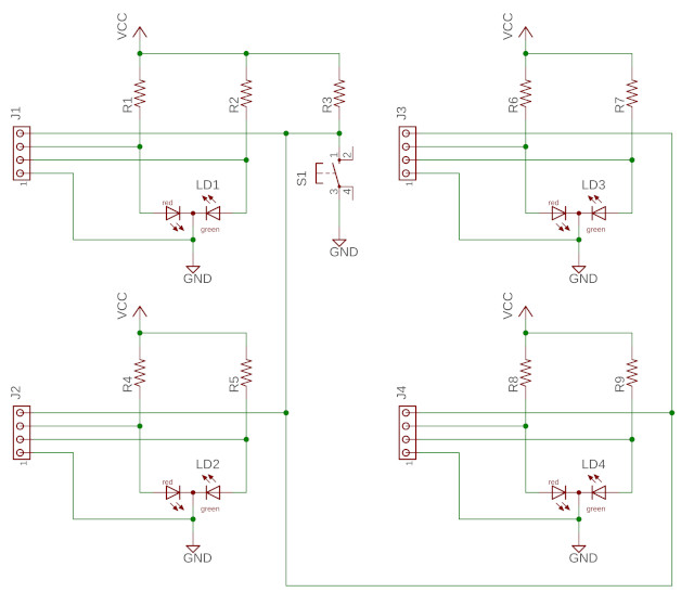
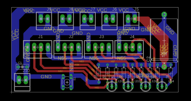
Figure 5 : Black box circuit diagram (top), PCB (bottom)
Each Pi controls one tri-colour LED and reads the common push switch. The common shutdown switch signal is connected to pin GPIO-16. The two LED control signals are connected to pins GPIO-20 and GPIO-21, as shown in figure 6.
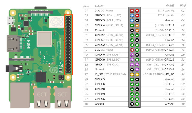
Figure 6: GPIO header.
Note, the LED circuit is simple, but not perhaps the best design, definitely could be better, as there is a possibility of "stressing" the LEDs. The LED control signals from the Raspberry Pi GPIO must ONLY be driven to either a logic-0 or a high-impedance state, never to a logic-1, as this would result in VCC being applied across the LED with no current limiting resistor. The resister values used in this circuit are dependent on forward voltage of the LED, but typical values would be 560, 470 or 330 ohms, the lower the value the brighter the LED. The resistor for the shutdown switch would typically be 10K, however, to simplify construction the same value as that used by the LEDs was used i.e. no wasted power issues as current only flows through the switch when it is pushed (ignoring leakage) and as this signal stops the Pi we are not worried about noise / contact bounce etc. A final thing to note, is that there is no power-on switch i.e. once the Raspberry Pis are shutdown you will need to cycle the power to turn them back on again i.e. the mains switch, or pull-out and push-back in the DC power jack.
The code below is used to control these LEDs and read the shutdown button. Confess this is not the best solution i.e. very open loop, no feedback from the Pi that it is shutting down, however, it does the job. After a year or so of usage not seeing any SDcard failures, well there was 1, but that could just be down to bad luck :).
import RPi.GPIO as GPIO
import threading
import time
import os

def flashLED_thread_function():
  GPIO.setup(21, GPIO.OUT)
  GPIO.output(21, GPIO.LOW)

  while True:
    GPIO.setup(20, GPIO.IN, pull_up_down=GPIO.PUD_UP)
    time.sleep(0.5)

    GPIO.setup(20, GPIO.OUT)
    GPIO.output(20, GPIO.LOW)
    time.sleep(0.5)

GPIO.setmode(GPIO.BCM)
GPIO.setup(16, GPIO.IN, pull_up_down=GPIO.PUD_UP)
GPIO.setup(20, GPIO.IN, pull_up_down=GPIO.PUD_UP)
GPIO.setup(21, GPIO.IN, pull_up_down=GPIO.PUD_UP)

os.system("sudo echo \"Power on : \" `/usr/bin/date` >> /usr/local/sbin/boot.log")
time.sleep(10)
GPIO.setup(20, GPIO.OUT)
GPIO.output(20, GPIO.LOW)

try:
  GPIO.wait_for_edge(16, GPIO.FALLING)
  print("shutdown -h now")
  time.sleep(1)
  flashLED = threading.Thread(target=flashLED_thread_function)
  flashLED.start()
  os.system("sudo sync /dev/mmcblk0")
  time.sleep(2)
  os.system("sudo killall sshd")
  time.sleep(2)
  os.system("sudo echo \"Power off : \" `/usr/bin/date` >> /usr/local/sbin/boot.log")
  time.sleep(10)
  os.system("sudo shutdown -h now")
  time.sleep(100)
except:
  pass

GPIO.cleanup()
Each Raspberry Pi has a range of network services installed:
Each Raspberry Pi also has a range of network tools installed:
Pi-1 in the Base node also has addition software installed: a Dynamic Host Configuration Protocol (DHCP) server. The IP address of ETH0 for Pi-1 is static i.e. fixed to 192.168.DESK.1, the IP addresses of Pi-2 and Pi-3 ETH0 interfaces are dynamically assigned by Pi-1. However, within the dhcpd.conf file on Pi-1 the MAC addresses of Pi-2 and Pi-3 ETH0 NICs are hard-coded to specific IP addresses i.e. 192.168.DESK.2 for Pi-2 and 192.168.DESK.3 for Pi-3, as shown below. If another host is connected to the spare port on the switch e.g. a laptop, this will be dynamically assigned an IP address within the range 192.168.DESK.10 to 192.168.DESK.253. For more info on DHCP refer here: (Link).
Note, the reason why Pi-2 and Pi-3 are not assigned static IP addresses is to allow students to see DHCP in action i.e. in a wireshark packet capture using dhclient commands.
default-lease-time 600;
max-lease-time 7200;

ddns-update-style none;

subnet 192.168.0.0 netmask 255.255.0.0 {
  range 192.168.90.10 192.168.90.253;
  option routers 192.168.90.1;
}

host pi-2 {
  hardware ethernet 80:6d:97:12:26:52;
  fixed-address 192.168.90.2;
}

host pi-3 {
  hardware ethernet 80:6d:97:10:da:d3;
  fixed-address 192.168.90.3;
}
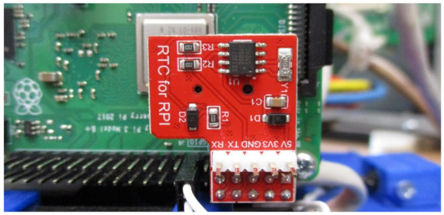
Figure 7: RTC module.
All Raspberry Pi in the Base node run a NTP server, however, Pi-1 has been fitted with a Real Time Clock (RTC) module, as shown in figure 7, to give some level of time synchronisation between the Raspberry Pis. Note, typically NTP relies on a pool of reference time servers, however, the lab network is not connected to the Internet. However, time synchronisation is further improved with the addition of a GPS NTP time server to the lab's network. For more information on NTP refer here: (Link).
The RTC module used by Pi-1 is based on the DS1307 RTC:
Pi-1 is configured to use the RTC as its time source, the following line was added to /boot/config.txt :
dtoverlay=i2c-rtc,ds1307
When initially installed you can confirm that this is working correctly (after a reboot) as the I2C address (0x68) used by the RTC has been removed i.e. i2cdetect -y 1 should give UU for address 0x68. The default fake-hwclock used in the absence of an RTC was disabled by running the following commands:
sudo apt-get -y remove fake-hwclock
sudo update-rc.d -f fake-hwclock remove
sudo systemctl disable fake-hwclock
The RTC hardware was then enabled by updating /lib/udev/hwclock-set to:
#!/bin/sh
# Reset the System Clock to UTC if the hardware clock from which it
# was copied by the kernel was in localtime.

dev=$1

if [ -e /run/udev/hwclock-set ]; then
  exit 0
fi

if [ -f /etc/default/rcS ] ; then
  . /etc/default/rcS
fi

# These defaults are user-overridable in /etc/default/hwclock
BADYEAR=no
HWCLOCKACCESS=yes
HWCLOCKPARS=
HCTOSYS_DEVICE=rtc0

if [ -f /etc/default/hwclock ] ; then
  . /etc/default/hwclock
fi

if [ yes = "$BADYEAR" ] ; then
  /sbin/hwclock --rtc=$dev --hctosys --badyear
else
  /sbin/hwclock --rtc=$dev --hctosys
fi

# Note 'touch' may not be available in initramfs
> /run/udev/hwclock-set
Finally, to set the OS to the correct time/date and update the RTC hardware to this time you can use the following commands:
sudo date -s "26 APR 2023 11:00:00"
sudo hwclock -w
sudo hwclock -r
The NTP config file /etc/ntp.conf for Pi-1 and Pi-2/Pi-3 are given below:
PI-1
----
# /etc/ntp.conf, configuration for ntpd; see ntp.conf(5) for help

driftfile /var/lib/ntp/ntp.drift

# Leap seconds definition provided by tzdata
leapfile /usr/share/zoneinfo/leap-seconds.list

# Enable this if you want statistics to be logged.

statistics loopstats peerstats clockstats
filegen loopstats file loopstats type day enable
filegen peerstats file peerstats type day enable
filegen clockstats file clockstats type day enable

logfile /var/log/ntp

server 127.127.1.0 prefer
fudge 127.127.1.0 stratum 10

# Local users may interrogate the ntp server more closely.
restrict 127.0.0.1

# Needed for adding pool entries
restrict source notrap nomodify noquery

# If you want to provide time to your local subnet, change the next line.
broadcast 192.168.90.255

PI-2/PI-3
---------
# /etc/ntp.conf, configuration for ntpd; see ntp.conf(5) for help

driftfile /var/lib/ntp/ntp.drift

# Leap seconds definition provided by tzdata
leapfile /usr/share/zoneinfo/leap-seconds.list

# Enable this if you want statistics to be logged.

statistics loopstats peerstats clockstats
filegen loopstats file loopstats type day enable
filegen peerstats file peerstats type day enable
filegen clockstats file clockstats type day enable

logfile /var/log/ntp

server 192.168.90.1 minpoll 4 maxpoll 4 iburst

# Local users may interrogate the ntp server more closely.
restrict 127.0.0.1

# Needed for adding pool entries
restrict source notrap nomodify noquery
Note, NTP servers are ranked by their stratum level. Stratum 0 is an atomic clock, this is not directly connected to the network. Stratum 1 is the NTP server connected to an atomic clock or GPS receiver. Stratum 2 is an NTP server that synchronises its system clock with the clock on a Stratum 1 server. Stratum 3 is an NTP server that is synchronised using a stratum 2 server, and so on. Stratum 15 is the lowest level i.e. its clock can not be used to synchronise another host. Stratum 16 defines an unsynchronised host.
The MikroTik router was added to the Base node to give students the chance to experiment with / setup a router. To me router config is an art, rather than a science :). The Base node is run headless i.e. there are no direct monitor or keyboard connections, therefore, I decided that the router should not form a core part of the Base node's "admin" network i.e. just in case the router is mis-configured (bricked), you still need access to a Raspberry Pi. Therefore, even if the router is misconfigured you can still SSH or VNC into each Raspberry Pi via the switch i.e. the 192 network, hopefully allowing the router to be fixed, failing that a factory reset can always be performed i.e. hold down the reset switch, plug in power, wait for LED flash, wait for router to reconfigure (takes a minute), then reset its config file. An example initial configuration is shown in figure 8. Note, no bridge, just IP addresses assigned to ports 1-4.
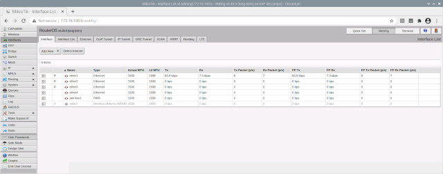
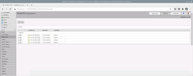
Figure 8: MikroTik config.
In the event of a mistake enter the following commands to reset a misconfigured MikroTik:
FACTORY DEFAULT RESET
---------------------
log into Pi-3
sudo ifconfig eth0:0 192.168.88.200 netmask 255.255.255.0 up
Open browser to http://192.168.88.1
Restore config using the web interface
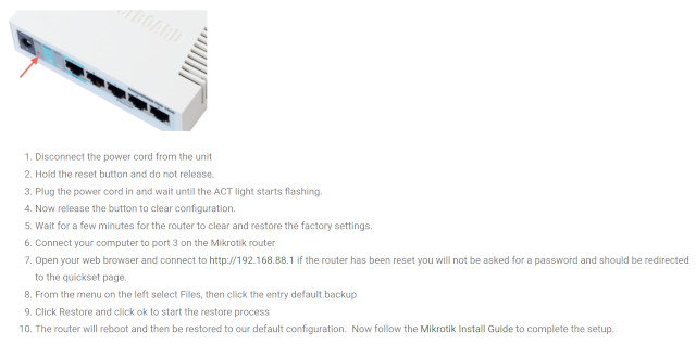
Figure 9: MikroTik factory default.
The hardware used to mount the Pis, switch and router are available below. When designing these the design aims were:
Confess i did not keep on top of the version control of the files used for the 3D printed and laser cut parts. Looking through my collection of files i found most of them, but i'm not sure if they are the final versions. What i found are shown in figures 10 and 11, and can be downloaded using the links below, buyer beware :).


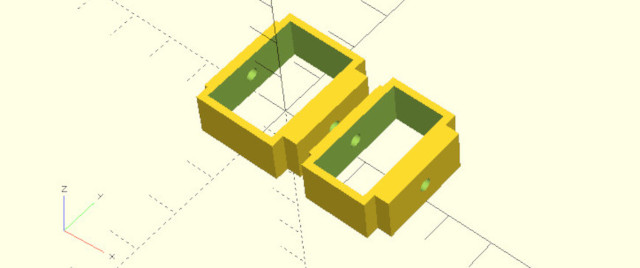
Figure 10: 3D printed parts.


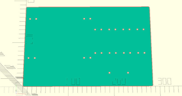
Figure 11: laser cut parts.

This work is licensed under a Creative Commons Attribution-NonCommercial-NoDerivatives 4.0 International License.
Contact email: mike@simplecpudesign.com