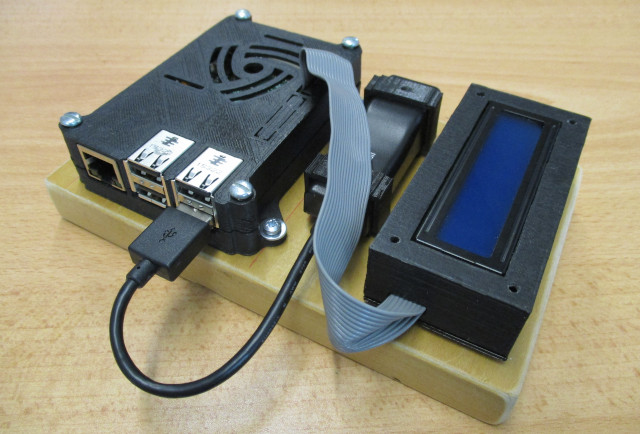
Figure 1 : Raspberry Pi name server system
As the hosts in the lab don't have access to the Internet, they don't have access to the department's DNS servers (Link) i.e. name servers that convert human readable host names into IP addresses. Before we look at the hardware used to create this node, we need to first cover a little background to give context to the choices i made :). The Domain Name System (DNS) is a hierarchical, distributed database spread across the world, mapping host names to IP addresses e.g. w2f5www.york.ac.uk. identifies the host (web server) w2f5www, which is in the domain (network) york.ac.uk.. Note, some people say the "S" in DNS is "server", not sure about that, so i'm sticking with "S" for system. The organisation of this database is broken down into different zones. These zones define who manages what areas in the DNS name space i.e. defines who controls the authoritative name servers that hold the final IP addresses for these hosts. Therefore, for the previous example a zone defines what server holds the entries that maps the host name w2f5www to its IP address 144.32.128.93. This domain name space is a hierarchical tree, as shown in figure 2.
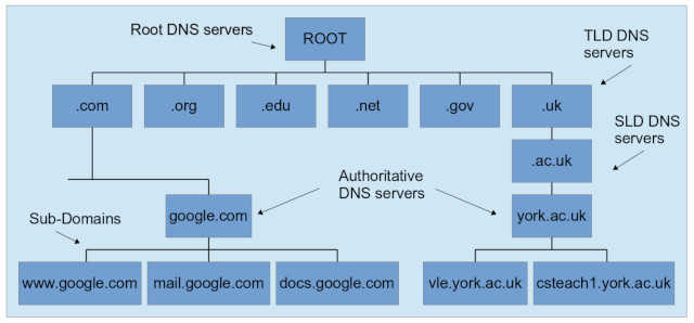
Figure 2 : DNS server hierarchy
At the top of the DNS tree is the root domain. Note, this is represented by the final '.' in w2f5www.york.ac.uk., you can find the location of your nearest root name server here: Link. DNS zones are typically organised as a top-level domain (TLD), then a second-level domain (SLD), then a server that acts as the authoritative name server for that domain (zone) i.e. the start of the authoritative area (SOA). Zones can extend down into subdomains, or multiple subdomains, which can be managed by the same server. So in the case of the previous example root=., TLD=uk, SLD=ac, SOA=york.
For the lab hardware we can setup a local DNS servers on the lab's internal network that can resolve the name to IP address mappings for any machine on the lab's network. Therefore, to approximate the DNS hierarchy used on the Internet we will breakdown the lab's name space (zones) as follows:
.lan                - The lab's top level domain i.e. the internal local area network.
.deskX.lan          - Desk SOA, each desk is responsible for resolving the names of the hosts on that desk.
pi-1.deskX.lan      - A "Fully" qualified name, identifying the host and the network it operates on.
We don't have root DNS servers in this model as there is only one TLD i.e .lan. The implementation of each desk's SOA name server could be done in a number of ways e.g. a docker container (Link), installing BIND on the Raspberry Pi (Link), or on the MikroTik router (Link). I decided to go for the MikroTik option, mostly just to move some the processing load off the Raspberry Pi. We are using Pi 4's in the base node so they are quite powerful for a Pi, but everything has its limits. The MikroTik router used in the lab is hap-lite, as shown in figure 3.
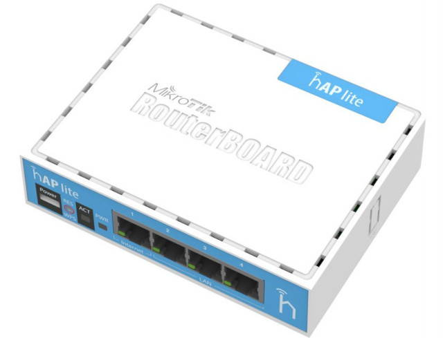
Figure 3 : DNS server hierarchy
The DNS server on the MikroTik is a "caching" DNS server i.e. it is not a fully featured DNS server like we could have if we were to install BIND. However, it will replicate a basic, no frills DNS system that can implement comparable functionality. On each Raspberry Pi we define the Pis name and domain in the /etc/hostname file, for Pi-1 on desk-85 this will contain:
pi-1.desk85.lan
To confirm a host's name and domain we can run the hostname command:

Figure 4 : hostname command
This returns the hostname as "pi-1" and its domain as "desk85.lan". To setup the this DNS server on the Mikrotik we can manually enter each machine's name and IP address as shown below:
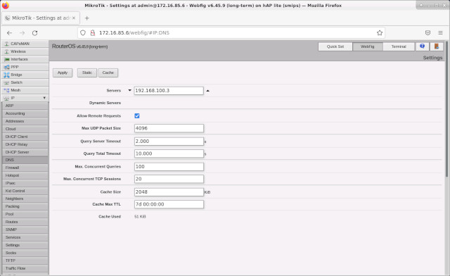
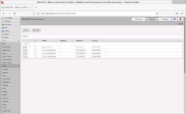
Figure 5 : MikroTik DNS config
To tell the Pi to use the MikroTik as its DNS server is a little tricky as you are fighting resolvconf and dhcpcd that implement the standard network setup on the Pi. To the best of my understanding adding the line resolvconf=NO stops the file resolv.conf being updated / overwritten, you can then manually set this file to your desired name server:
domanin desk85.lan
nameserver 172.16.85.6
To test that this is all working correctly we can use the dig command:
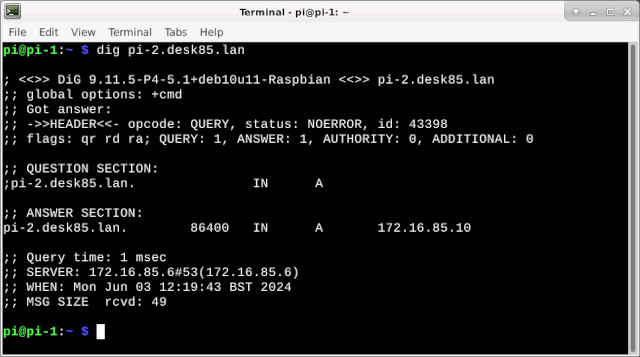
Figure 6 : dig command
This DNS server will resolve DNS queries for the three Raspberry Pis on each base node. However, to resolve DNS queries to hosts on other desks we will need to access a different name server e.g. a MikroTik on a different desk, a MikroTik in a different DNS zone. This functionality would be implemented by the ".lan" DNS server i.e. redirecting a queries to another desk. However, we now run into the issue that the MikroTik doesn't really define a SOA i.e. a DNS zone, rather it just holds / caches local IP addresses. Therefore, i decided to implement this functionality using a "nonstandard" solution i.e. i bodged it :). For me i can justify this on the ground that:
Therefore, to achieve the desired functionality of resolving DNS queries for other desks, you could hard code the lab's DNS information into the TLD server i.e. for ".lan". This is not the most elegant solution, but as this hardware is used for teaching, as a demonstrator, not a real world solution, it ticks all the boxes i.e. it just needs to demonstrate the points i'm trying to highlight / make in the lab script. So, yes, this solution does go against the previously defined DNS hierarchy used on the Internet, but it works and this solution does allow me to introduce and hopefully inspire some students to build their own Pi-hole: Link :).

Figure 7 : Pi-hole
To steal a quote from Pi-hole Wiki page (Link):"Pi-hole is a Linux network-level advertisement and Internet tracker blocking application which acts as a DNS sinkhole and optionally a DHCP server, intended for use on a private network. It is designed for low-power embedded devices with network capability, such as the Raspberry Pi, but can be installed on almost any Linux machine. Pi-hole has the ability to block traditional website advertisements as well as advertisements in unconventional places, such as smart TVs and mobile operating system advertisements ...
Pi-hole makes use of a modified dnsmasq called FTLDNS, cURL, lighttpd, PHP and the AdminLTE Dashboard to block DNS requests for known tracking and advertising domains. The application acts as a DNS server for a private network (replacing any pre-existing DNS server provided by another device or the ISP), with the ability to block advertisements and tracking domains for users' devices. It obtains lists of advertisement and tracking domains from a configurable list of predefined sources, and compares DNS queries against them. If a match is found within any of the lists, or a locally configured blocklist, Pi-hole will refuse to resolve the requested domain and respond to the requesting device with a dummy address ..."
Pi-hole gives a nice web interface showing the time and frequency of DNS traffic, also like the MikroTik router you can define local DNS entries as shown below:
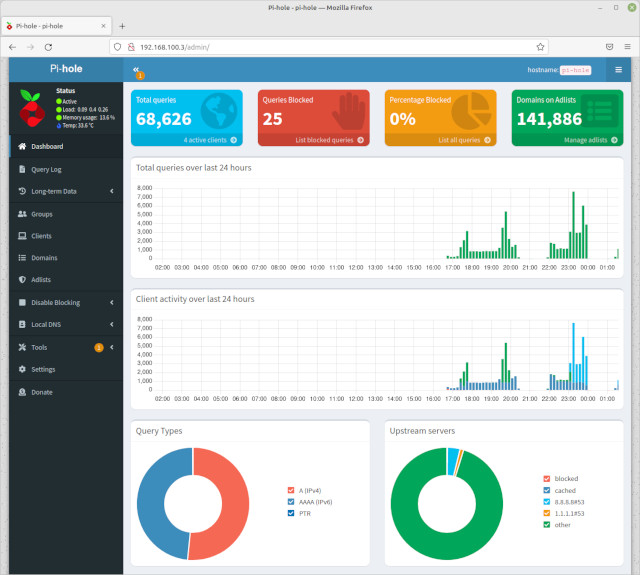
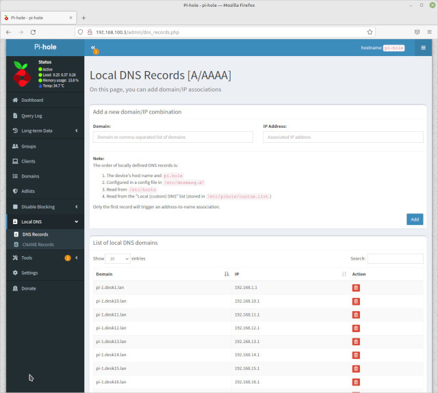
Figure 8 : Pi-hole config
These local DNS records could be entered manually via the web interface, but to save time you can write a script to update the custom.list file automatically, as shown below. Note, need to change the {1..85} for loop to be sh friendly.
#!/bin/bash

echo -n > custom.list

for i in {1..85};
do
  #echo $i
  for j in 1 2 3
  do
    echo 192.168.$i.$j pi-$j.desk$i.lan >> custom.list
  done
done
The final step is to point the MikroTik router in each base node to this DNS server i.e. 192.168.100.3, as shown in figure 5. Again to test if everything is work we can use the dig command.
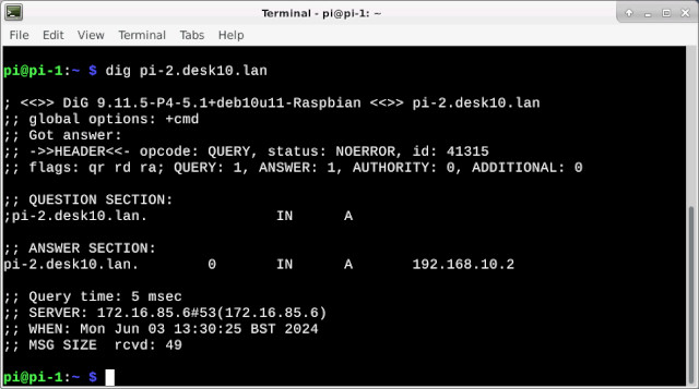
Figure 9 : dig command
This all work fine, but the eagle eyed amongst you will have spotted that the MikroTik (172.16.85.4/30) and the Pi-hole (192.168.0.0/16) are on different networks, therefore, some routing rules are required. Initially for testing i bypassed this problem by using the spare port on the MikroTik to give the router direct access to the 192.168.0.0/16 network and set the Pi-holes GW as Pi-1, as shown in figure 10.
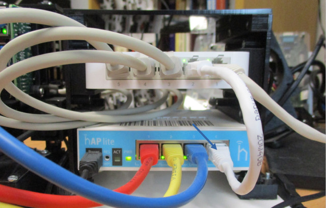


Figure 10 : testing setup
This setup proved that things could work, but isn't a practical solution i.e. all traffic on the network going to Pi-1 desk85 :). Therefore, for each desk we need a routing rule on Pi-hole to forward the DNS response to Pi-1 on the base node, which in turn will route this packet to the MikroTiK. To specify these routes we can add these to the file /etc/dhcpcd.exit-hook, as shown below:
# add persistent routes:
/sbin/route add -net 172.16.85.4/30 gw 192.168.85.1
To generate these entries for every desk we can use this script:
#!/bin/bash

echo "# add persistent routes:" > /etc/dhcpcd.exit-hook

for i in {1..85};
do
  echo /sbin/route add -net 172.16.$i.4/30 gw 192.168.$i.1 >> /etc/dhcpcd.exit-hook
done
In addition to this we need to update the MikroTik, to free up the spare port, adding a route to the 192.168.0.0./16 network, as shown in figure 11. Note, the Pi-hole routing table is now a little on the big size, so difficult to screen capture, but you get the idea :).


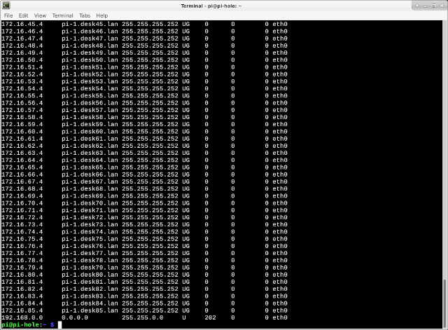
Figure 11 : Pi-hole and MikroTik routing rules.
A big thanks to Dean for spotting that i had initially setup the MikroTik route to use an interface, rather than an IP address, which broke everything and a second thanks for spotting that the Pi-holes default TTL is 2 seconds and that was why the MikroTik was "not" caching lookups. Therefore, the final changes to the Pi-hole are shown in figure 12.
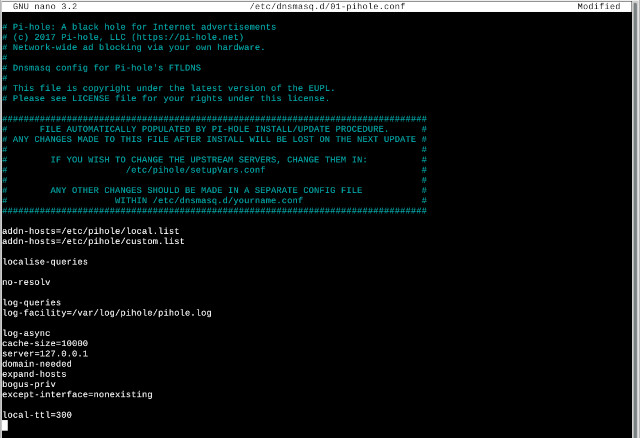
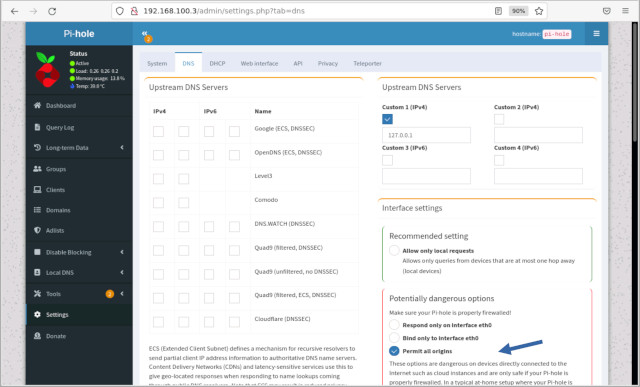
Figure 12 : Pi-hole updates.
To make the TTL change persistent i should read the Pihole docs, but being lazy i added a @reboot to crontab :).
#!/bin/sh
if test `cat /etc/dnsmasq.d/01-pihole.conf | grep -c ttl` -eq 0
then
  echo local-ttl=300 >> /etc/dnsmasq.d/01-pihole.conf
  /usr/local/pihole restartdns
fi
The hardware used to implement the Pi-Hole server is a Pi-2, i added a second USB-2-Ethernet adaptor, not really used, but useful when you need to install software, as you can just plug in an Internet connected cable into this socket to DHCP etc, without having to reconfigure ETH0. As always this hardware has a 16x2 LCD display. This time it is connected to the Pi using a 4bit parallel bus, rather than an I2C bus (just what i had to hand). Code to implement the display was based on the code from this web site: Link. The final code is shown below, note, need to update the disk size code.
# The wiring for the LCD is as follows:
# 1 : GND
# 2 : 5V
# 3 : Contrast (0-5V)*
# 4 : RS (Register Select)
# 5 : R/W (Read Write)       - GROUND THIS PIN
# 6 : Enable or Strobe
# 7 : Data Bit 0             - NOT USED
# 8 : Data Bit 1             - NOT USED
# 9 : Data Bit 2             - NOT USED
# 10: Data Bit 3             - NOT USED
# 11: Data Bit 4
# 12: Data Bit 5
# 13: Data Bit 6
# 14: Data Bit 7
# 15: LCD Backlight +5V**
# 16: LCD Backlight GND

import RPi.GPIO as GPIO
import time
import datetime

import os
import subprocess
import re

import psutil

# Define GPIO to LCD mapping
LCD_RS = 4
LCD_E  = 14
LCD_D4 = 15
LCD_D5 = 17
LCD_D6 = 18
LCD_D7 = 27


# Define some device constants
LCD_WIDTH = 16    # Maximum characters per line
LCD_CHR = True
LCD_CMD = False

LCD_LINE_1 = 0x80 # LCD RAM address for the 1st line
LCD_LINE_2 = 0xC0 # LCD RAM address for the 2nd line

# Timing constants
E_PULSE = 0.0005
E_DELAY = 0.0005

def lcd_init():
    # Initialise display
    lcd_byte(0x33,LCD_CMD) # 110011 Initialise
    lcd_byte(0x32,LCD_CMD) # 110010 Initialise
    lcd_byte(0x06,LCD_CMD) # 000110 Cursor move direction
    lcd_byte(0x0C,LCD_CMD) # 001100 Display On,Cursor Off, Blink Off
    lcd_byte(0x28,LCD_CMD) # 101000 Data length, number of lines, font size
    lcd_byte(0x01,LCD_CMD) # 000001 Clear display
    time.sleep(E_DELAY)

def lcd_byte(bits, mode):
    # Send byte to data pins
    # bits = data
    # mode = True  for character
    #        False for command

    GPIO.output(LCD_RS, mode) # RS

    # High bits
    GPIO.output(LCD_D4, False)
    GPIO.output(LCD_D5, False)
    GPIO.output(LCD_D6, False)
    GPIO.output(LCD_D7, False)

    if bits&0x10==0x10:
        GPIO.output(LCD_D4, True)
    if bits&0x20==0x20:
        GPIO.output(LCD_D5, True)
    if bits&0x40==0x40:
        GPIO.output(LCD_D6, True)
    if bits&0x80==0x80:
        GPIO.output(LCD_D7, True)

    # Toggle 'Enable' pin
    lcd_toggle_enable()

    # Low bits
    GPIO.output(LCD_D4, False)
    GPIO.output(LCD_D5, False)
    GPIO.output(LCD_D6, False)
    GPIO.output(LCD_D7, False)

    if bits&0x01==0x01:
        GPIO.output(LCD_D4, True)
    if bits&0x02==0x02:
        GPIO.output(LCD_D5, True)
    if bits&0x04==0x04:
        GPIO.output(LCD_D6, True)
    if bits&0x08==0x08:
        GPIO.output(LCD_D7, True)

    # Toggle 'Enable' pin
    lcd_toggle_enable()

def lcd_toggle_enable():
    # Toggle enable
    time.sleep(E_DELAY)
    GPIO.output(LCD_E, True)
    time.sleep(E_PULSE)
    GPIO.output(LCD_E, False)
    time.sleep(E_DELAY)

def lcd_string(message,line):
    # Send string to display
    message = message.ljust(LCD_WIDTH," ")

    lcd_byte(line, LCD_CMD)

    for i in range(LCD_WIDTH):
        lcd_byte(ord(message[i]),LCD_CHR)

def convertUnits(B):
    """Return the given bytes as a human friendly KB, MB, GB, or TB string."""
    B = float(B)
    KB = float(1024)
    MB = float(KB ** 2) # 1,048,576
    GB = float(KB ** 3) # 1,073,741,824
    TB = float(KB ** 4) # 1,099,511,627,776

    if B < KB:
        return '{0} {1}'.format(B,'Bytes' if 0 == B > 1 else 'Byte')
    elif KB <= B < MB:
        return '{0:.2f} KB'.format(B / KB)
    elif MB <= B < GB:
        return '{0:.2f} MB'.format(B / MB)
    elif GB <= B < TB:
        return '{0:.2f} GB'.format(B / GB)
    elif TB <= B:
        return '{0:.2f} TB'.format(B / TB)

print( "display started" )

GPIO.setwarnings(False)
GPIO.setmode(GPIO.BCM)       # Use BCM GPIO numbers
GPIO.setup(LCD_E, GPIO.OUT)  # E
GPIO.setup(LCD_RS, GPIO.OUT) # RS
GPIO.setup(LCD_D4, GPIO.OUT) # DB4
GPIO.setup(LCD_D5, GPIO.OUT) # DB5
GPIO.setup(LCD_D6, GPIO.OUT) # DB6
GPIO.setup(LCD_D7, GPIO.OUT) # DB7

# Initialise display
lcd_init()

# Main program block

messages = []

def main():
    previous_bytes_rx = 0
    previous_bytes_tx = 0

    while True:

      lcd_string("RaspberryPi DNS", LCD_LINE_1)
      lcd_string("Pi Hole", LCD_LINE_2)

      time.sleep(5) # second delay

      cpu_usage = psutil.cpu_percent()
      mem_free = int(re.split('=', re.findall('free=[0-9]*', str(psutil.virtual_memory()))[0])[1])

      outputString1 = "CPU: " + str(cpu_usage)
      outputString2 = "MEM: " + str(convertUnits(mem_free))

      lcd_string(outputString1, LCD_LINE_1)
      lcd_string(outputString2, LCD_LINE_2)

      time.sleep(5) # second delay

      disk_1_free = int(re.split('=', re.findall('free=[0-9]*', str(psutil.disk_usage('/')))[0])[1])
      disk_2_free = int(re.split('=', re.findall('free=[0-9]*', str(psutil.disk_usage('/home')))[0])[1])

      outputString1 = "DSK1: " + str(convertUnits(disk_1_free))
      outputString2 = "DSK2: " + str(convertUnits(disk_2_free))

      lcd_string(outputString1, LCD_LINE_1)
      lcd_string(outputString2, LCD_LINE_2)

      time.sleep(5) # second delay

      bytes_rx = int(re.split('=', re.findall('bytes_recv=[0-9]*', str(psutil.net_io_counters()))[0])[1])
      bytes_tx = int(re.split('=', re.findall('bytes_sent=[0-9]*', str(psutil.net_io_counters()))[0])[1])

      rx_network_usage = round((bytes_rx - previous_bytes_rx)/8, 1)
      previous_bytes_rx = bytes_rx

      tx_network_usage = round((bytes_tx - previous_bytes_tx)/8, 1)
      previous_bytes_tx = bytes_tx

      outputString1 = "IN: " + str(convertUnits(rx_network_usage))
      outputString2 = "OUT: " + str(convertUnits(tx_network_usage))

      #print( str(psutil.net_io_counters()))

      lcd_string(outputString1, LCD_LINE_1)
      lcd_string(outputString2, LCD_LINE_2)

      time.sleep(5) # second delay

      ip_addr = str(subprocess.check_output("hostname -I", shell=True)).split(' ')
      outputString1 = "IP ADDR ETH0: "
      outputString2 = ip_addr[0].replace("b'","")

      lcd_string(outputString1, LCD_LINE_1)
      lcd_string(outputString2, LCD_LINE_2)

      time.sleep(5) # second delay

      outputString1 = "IP ADDR ETH1: "
      outputString2 = ip_addr[2]

      lcd_string(outputString1, LCD_LINE_1)
      lcd_string(outputString2, LCD_LINE_2)

      time.sleep(5) # second delay

if __name__ == '__main__':

  try:
    main()
  except KeyboardInterrupt:
    pass
  finally:
    lcd_string("Goodbye!",LCD_LINE_1)
    GPIO.cleanup()
So, finally we have a DNS system for the lab which may not tick all the boxes, but it will illustrate the points i am trying to explain in the labs.

This work is licensed under a Creative Commons Attribution-NonCommercial-NoDerivatives 4.0 International License.
Contact email: mike@simplecpudesign.com