As the hosts on the labs network are not connected to the Internet they don’t have access to public time servers. Therefore, each Pi on each Base node could have a different internal time. To minimise this error Pi-1 in each Base node is configured with a real time clock (RTC) module, with a battery backup, discussed here: Link. This Pi acts as a Network Time Protocol (NTP) server, allowing each Raspberry Pi within the Base node to obtain a basic level of time synchronisation. However, these RTC modules are not perfect i.e. clock drift can occur when not powered. Therefore, to provide an “external” reference clock for the labs internal network a Global Positioning System (GPS) module is used on the Time node, shown in figure 1 i.e. to create a stratum 1 NTP server.

Figure 1: GPS module.
The GPS module is connected to the Pi via the 40 pin GPIO header shown in figure 2, using the serial port (TXD0, RXD0) and GPIO18 pins.
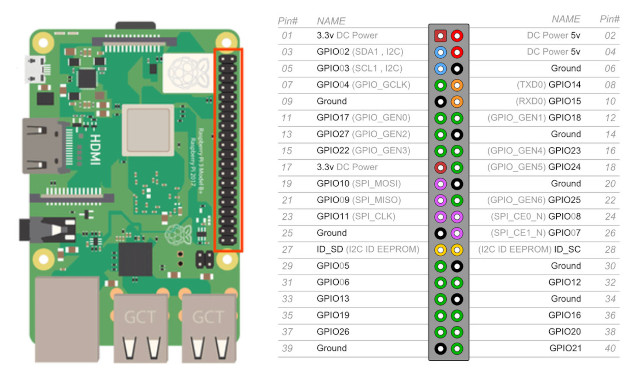
Figure 2: GPIO header.
To setup this GPS module the following software was installed:
sudo apt-get install pps-tools gpsd gpsd-clients python-gps
Next, the following lines are added to /boot/config.txt
[all]
enable_uart=1
init_uart_baud=9600
dtoverlay=pps-gpio,gpiopin=18

arm_64bit=0

core_freq=500
sdram_freq=500
over_voltage=2
gpu_mem=32
Note, i'm using an old Pi-2 for this NTP server so need to flag its not 64bit, not sure why, but some web pages say its need. Turned on serial and turned off serial login etc using raspiconfig tool. As a rule of thumb using the NTP protocol we should be able to synchronise a system clock to +/- 5 to 100 milli-seconds, depending on network delays, the quality of the time servers etc. Using a GPS receiver it is possible to get more accurate results, however, this is complicated by the delays in accessing this data across the serial port. To help reduce these errors GPS receivers typically also have a Pulse Per Second (PPS) pin that outputs a precision 1Hz square wave. Supposedly, this can be used by the OS to allow synchronisation to a few milliseconds, but i confess i'm not sure how reliable this is i.e. given OS overheads delays etc. Note, to state the obvious i also found that the PPS signal is quite dependent on the GPS signal strength i.e. dependant on your environment, line of sight etc. Therefore, in electrically noisy, shielded labs GPS signal strength was an issue :)
The GPS module's gpsd daemon is configure in /etc/default/gpsd:
START_DAEMON="true"

DEVICES="/dev/ttyAMA0 /dev/pps0"

# Other options you want to pass to gpsd
GPSD_OPTIONS="-n"

# Automatically hot add/remove USB GPS devices via gpsdctl
USBAUTO="true"
To enable the PPS module in the OS the following line is added to /etc/modules:
pps-gpio
To configure the NTP server the /etc/ntp.conf file is updated to:
# /etc/ntp.conf, configuration for ntpd; see ntp.conf(5) for help

driftfile /var/lib/ntp/ntp.drift

# Leap seconds definition provided by tzdata
leapfile /usr/share/zoneinfo/leap-seconds.list

# Enable this if you want statistics to be logged.

statistics loopstats peerstats clockstats
filegen loopstats file loopstats type day enable
filegen peerstats file peerstats type day enable
filegen clockstats file clockstats type day enable

logfile /var/log/ntp

#server 127.127.1.0 prefer
#fudge 127.127.1.0 stratum 10

server 127.127.28.0 minpoll 4 maxpoll 4 prefer
fudge 127.127.28.0 time1 0.000 flag1 1 refid GPS

server 127.127.22.0 minpoll 4 maxpoll 4
fudge 127.127.22.0 flag3 1 refid PPS

restrict -4 default kod limited nomodify notrap nopeer

# Local users may interrogate the ntp server more closely.
restrict 127.0.0.1

broadcast 192.168.255.255
The Pi is connected to the GPS module using the following pins on the GPIO header:
Note, the serial port must be crossed i.e. RX to TX and TX to RX. To test if the PPS module is loaded on the Time node run:
lsmod | grep pps
To check that PPS pulses are being received run:
sudo ppstest /dev/pps0
To test if the GPS module has locked onto the required satellites run:
gpsmon
Alternatively, the command line tool cgps give a little more info. I had lots of joys with the PPS signal, not sure why, atmospheric conditions, EMI from some electronics, but some days its just not happy. I tried commenting out the different lines (above), adding new lines etc, but sometimes the PPS signal does not work i.e. i get a connection timeout, as shown in figure 3. When running this is an easy error to spot as the red LED on the GPS module stops flashing i.e. when working it flashes once per second. One thing that seems to fix it is to stand the hardware outside on the windsill, not a permanent solution, so im guessing interference, weak signal?

Figure 3: PPS timeout.
Another test that shows that something is not working is that when testing the GPS using the cgps command line tool you can see satellites listed, you can see the time, but these satellites are all listed as not used (N), rather than used (Y) as shown in figure 4.
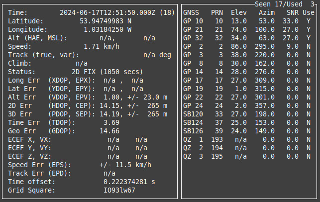
Figure 4: cgps test output.
At the moment its all works ok, so PPS is enabled. However, when PPS stops working the NTP server does not sync, not sure why. Another key thing to remember is that if the time is not correct you need to stop then start the ntpd.service i.e. give it a kick to update the time :). To test if the NTP service is running on the Pi run:
sudo systemctl status ntp.service
To examine the NTP server’s status run:
ntpq -4p
ntpstat
Note, normally the NTP service can take a lonnnnng time to sync to the GPS clock e.g. 10+ minutes. The process of updating a system's clock using NTP is sloooooow i.e. NTP slowly adjusts a system's clock to bring it into synchronisation with the reference clock, rather than instantly updating the clock, unless you get/issue an NTP panic then its really quick :).
sudo systemctl stop ntp.service
sudo ntpd -gq
sudo systemctl start ntp.service
Initial testing in my office went to plan, however, when moved into the lab i.e. a room containing lots of computers, the GPS module had the same difficulties as before i.e. locking onto satellites. I assumed this was due to increased background electrical interference. However, reading around the GPS antenna is a patch antenna (Link), the gain of this type of antenna can be significantly improved by placing it on a ground plane i.e. a conductive surface. This indeed fixed the problem. The final system is shown in figure 5. The size of the ground plane (aluminium sheet) was determined by the space available, rather than being designed, in this case 20cm x 20cm. Smaller / bigger sizes were not tested. Note, i guess the ground plane may also be adding some shielding from the Pi's electromagnetic interference (EMI) (Link), also blocking reflected radio signals from the satellite that form destructive interference paths, or it may all be in my head?
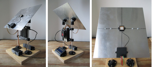
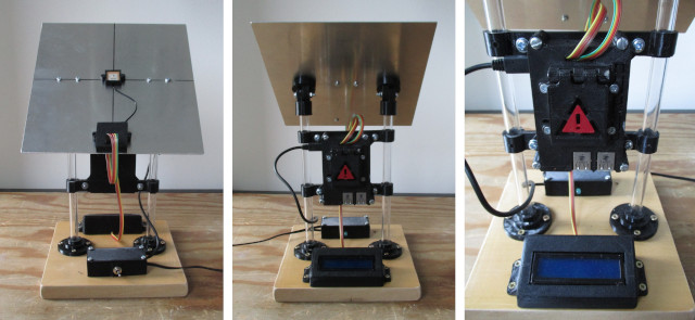
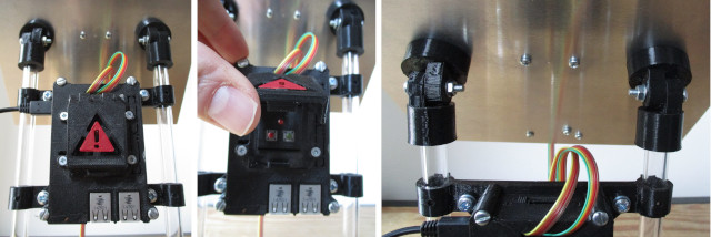
Figure 5: GPS system
The Raspberry Pi and its case were from an old project (link below) and uses an old Pi1-b, an original Pi :). The two push buttons under the hinged front box are the shutdown (green) and reset (red) buttons. 3D printer STL files are available here:


Figure 6: 3D printed parts

This work is licensed under a Creative Commons Attribution-NonCommercial-NoDerivatives 4.0 International License.
Contact email: mike@simplecpudesign.com