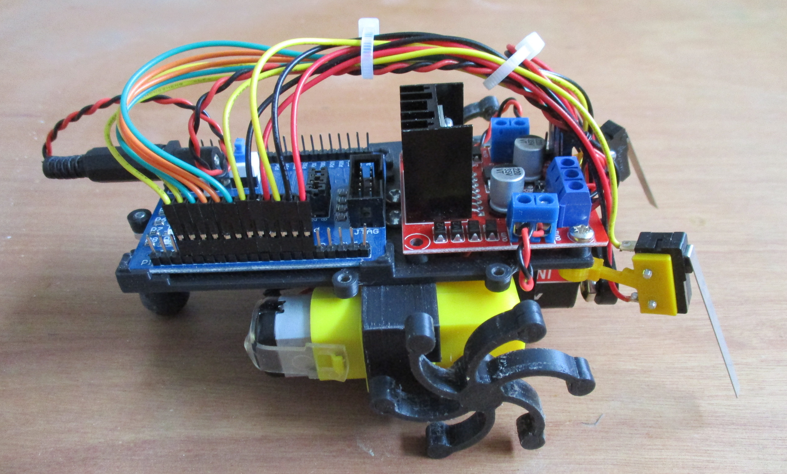
Figure 1 : robot cockroach
All new and improved robot cockroach, well i added micro-switches :). Designed over a series of SYS1 workshops. If you would like to a recap how this beast was designed the original is available here: (Link). Otherwise, below are the updated instructions on how to build your robot.
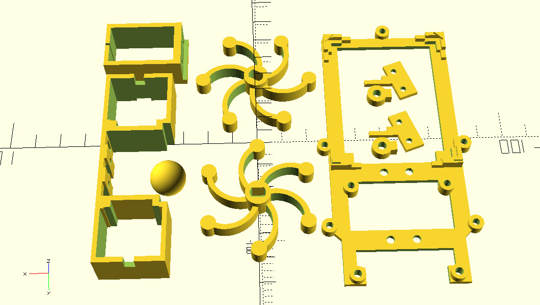
Figure 2 : chassis parts
Reduced the number of parts when compared to the original, mainly owing to the battery. Its surprising how much PB3 9V batteries vary in size, so decided to go for a "clip" style of mount, to help accommodate these variation. The chassis is divided into a number of parts to maximise strength, such that 3D printed laminations always run in the correct axis. The parts shown in figure 2 form the: ladder chassis, battery clip, motor bracket, rear skid, left\right "wheels" and front arms. Mounting points are taped using an M3 drill-tap and joined together using M3 x 6 bolts.
The openScad 3D models and STL files are available here:
The first things you learn when using 3D printed parts is that they can come with a large amount of clean-up time, so you may need to use a Stanley knife / small needle file to remove any stringing, lumps and bumps, as shown in figure 3. Use a craft knife to cut off the larger lumps, a sawing action is normally better than force, this helps control the follow through and saves slicing your fingers. Use a needle file to smooth down the inner surfaces. Note, on the motor bracket, make sure you cut and file out the cut-outs for the motor locating pegs (shown later in fig 8, left frame), and smooth down the back of the motor bracket, otherwise you will have problems removing the motors from this bracket.
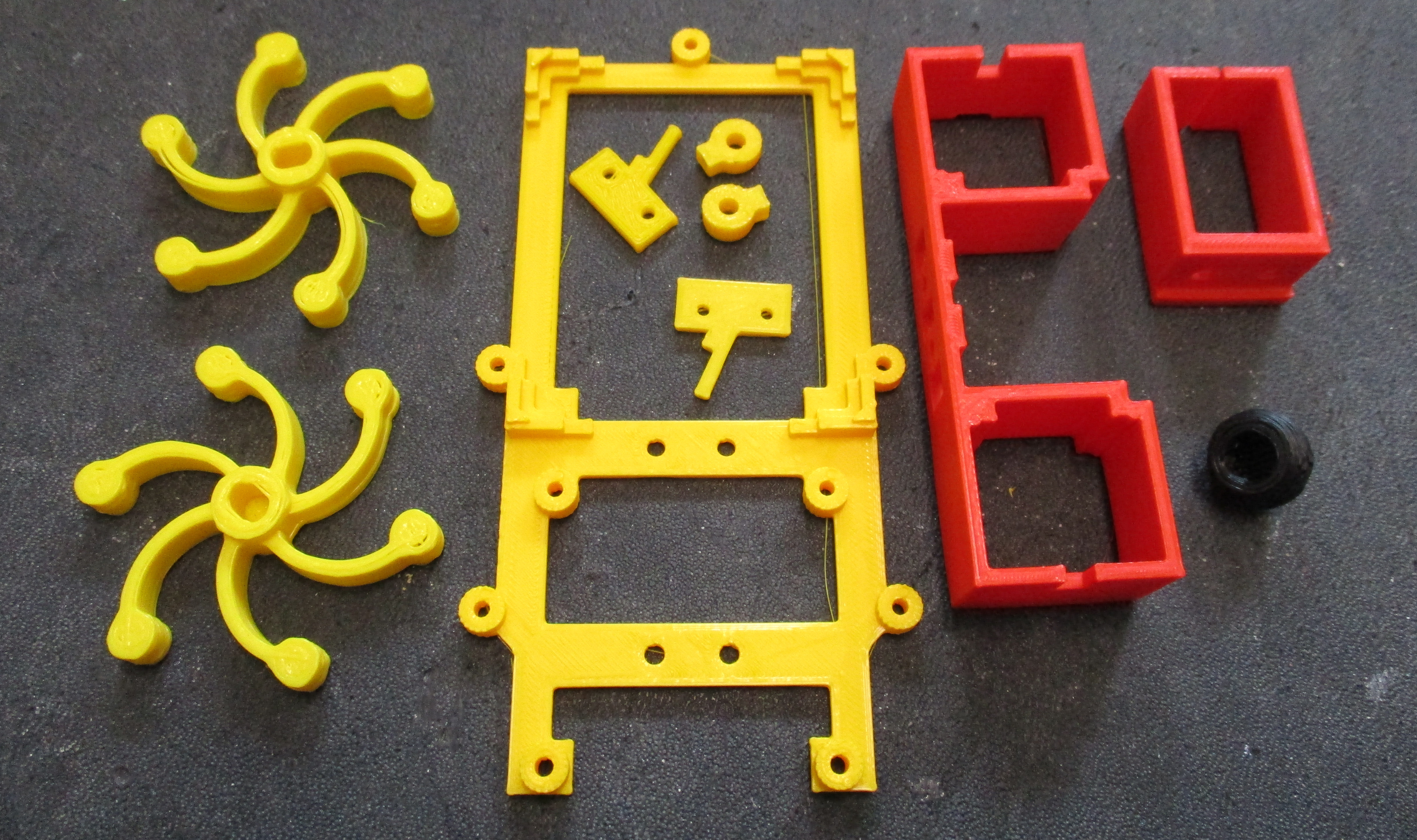
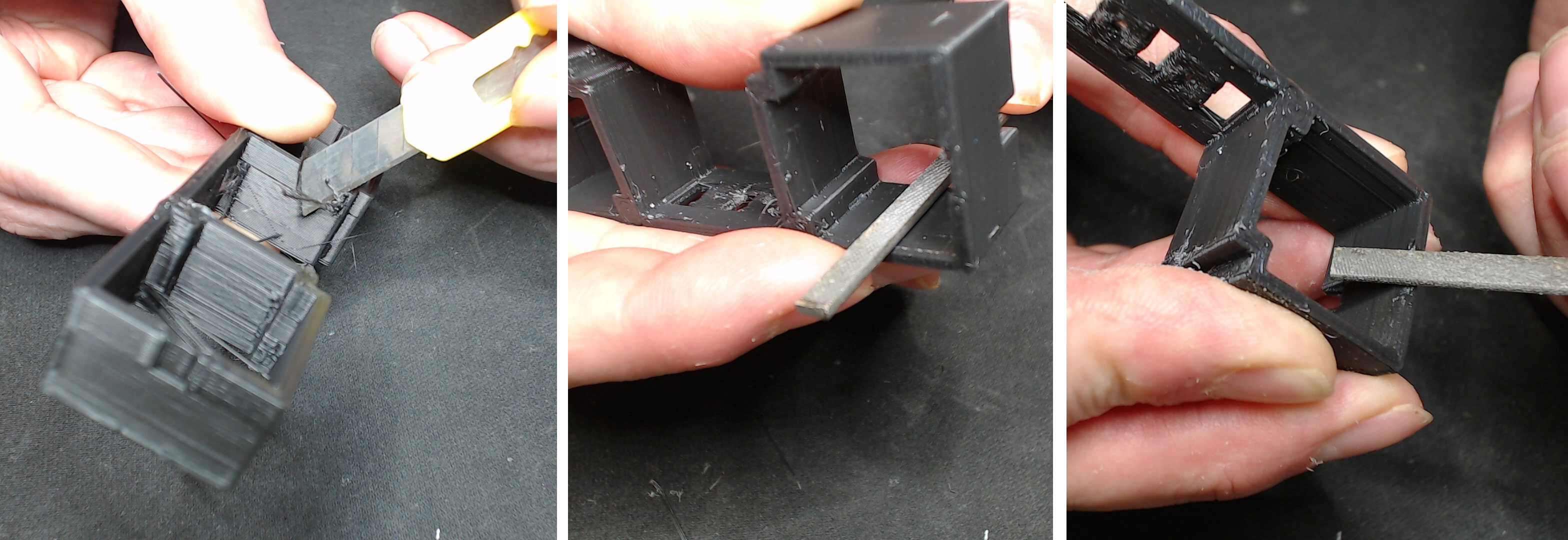
Figure 3 : 3D printed parts
The wheels are a push / friction fit onto the each drive shaft. Check each hole for any obstructions, smooth inner surfaces using a needle file if needed. If its a tight "friction" fit you may need to chamfer the edge of the hole. IMPORTANT, when inserting the drive shaft do no press on the yellow gearbox / case! Place the rear of the drive shaft on the table (fig 4, right frame), then using your thumb to push the wheel onto the drive shaft i.e. force is through drive shaft onto the desk, not through the gearbox. Test fit, if needed remove and file down the inner surface a little more. IMPORTANT, when removing a wheel you may need to gently, incrementally lever / rock the wheel up the drive shaft. Alternatively, if the wheel is a little loose, try some hot glue :).
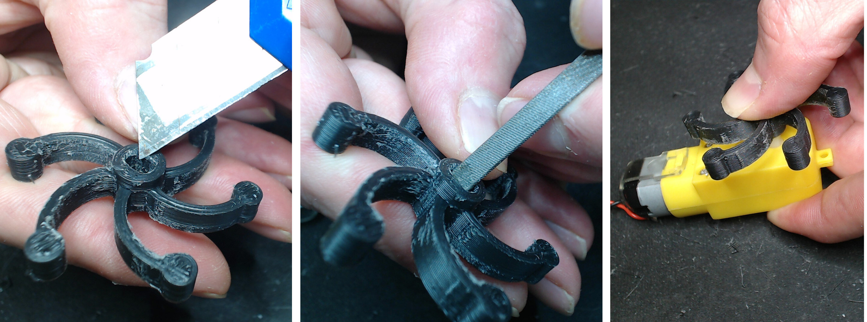
Figure 4 : attaching wheels
Before inserting each motor into the 3D printed bracket, solder wires onto their terminals, do this with the wheels attached (stops motor falling over). Use 13 cm, twisted red and black, 7 strand wire (not single core), as shown in figure 5.
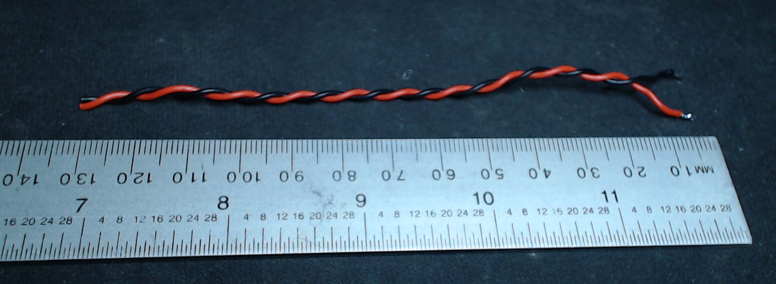
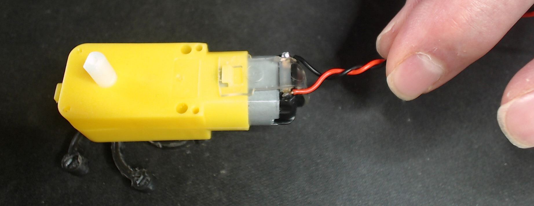
Figure 5 : soldering motor leads and inserting motors
The chassis and battery clips have mounting points that need to be either drilled or tapped, as shown in figure 6, using the M3 drill or M3-drill-tap hand tools. To use these simply insert into the existing 3D printed hole, apply gentle downwards pressure and twist in a clockwise direction. When drilling a hole watch out for your fingers and the desk. IMPORTANT, do drill on top of a scrap piece of wood not the desk. When tapping a hole make sure you cut threads all the way through the plastic. IMPORTANT, when tapping a hole i.e. cutting threads into the plastic, do regularly unscrew\remove the tap from the hole, so that you can remove plastic from the cutting teeth i.e. break the chips, if you don't you can strip the thread you are cutting.

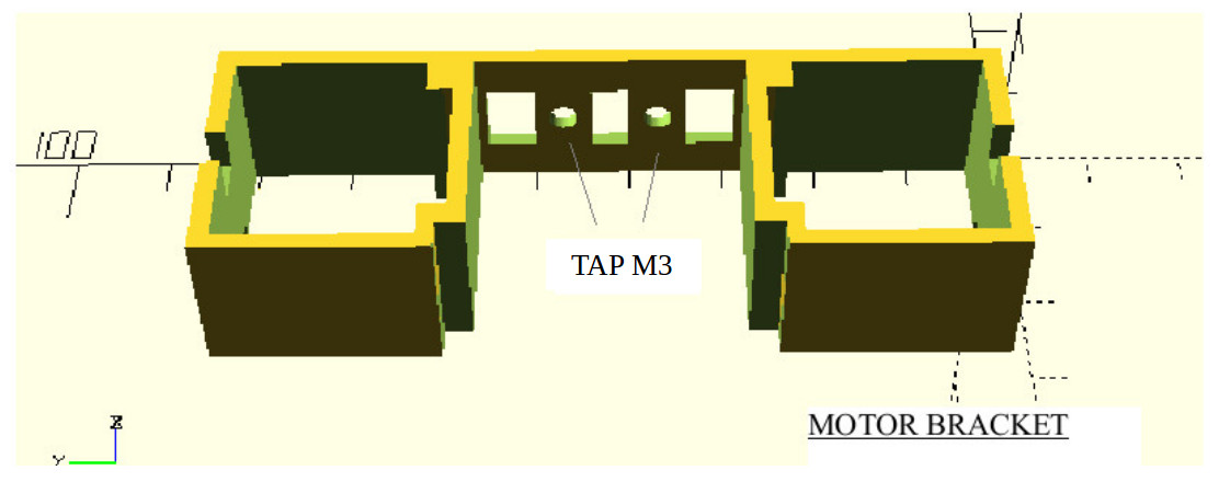
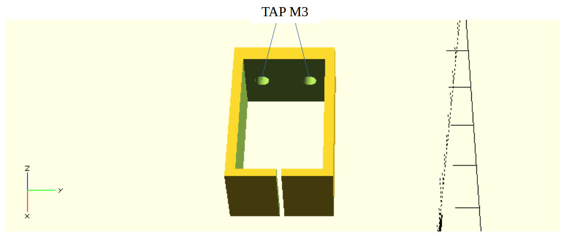
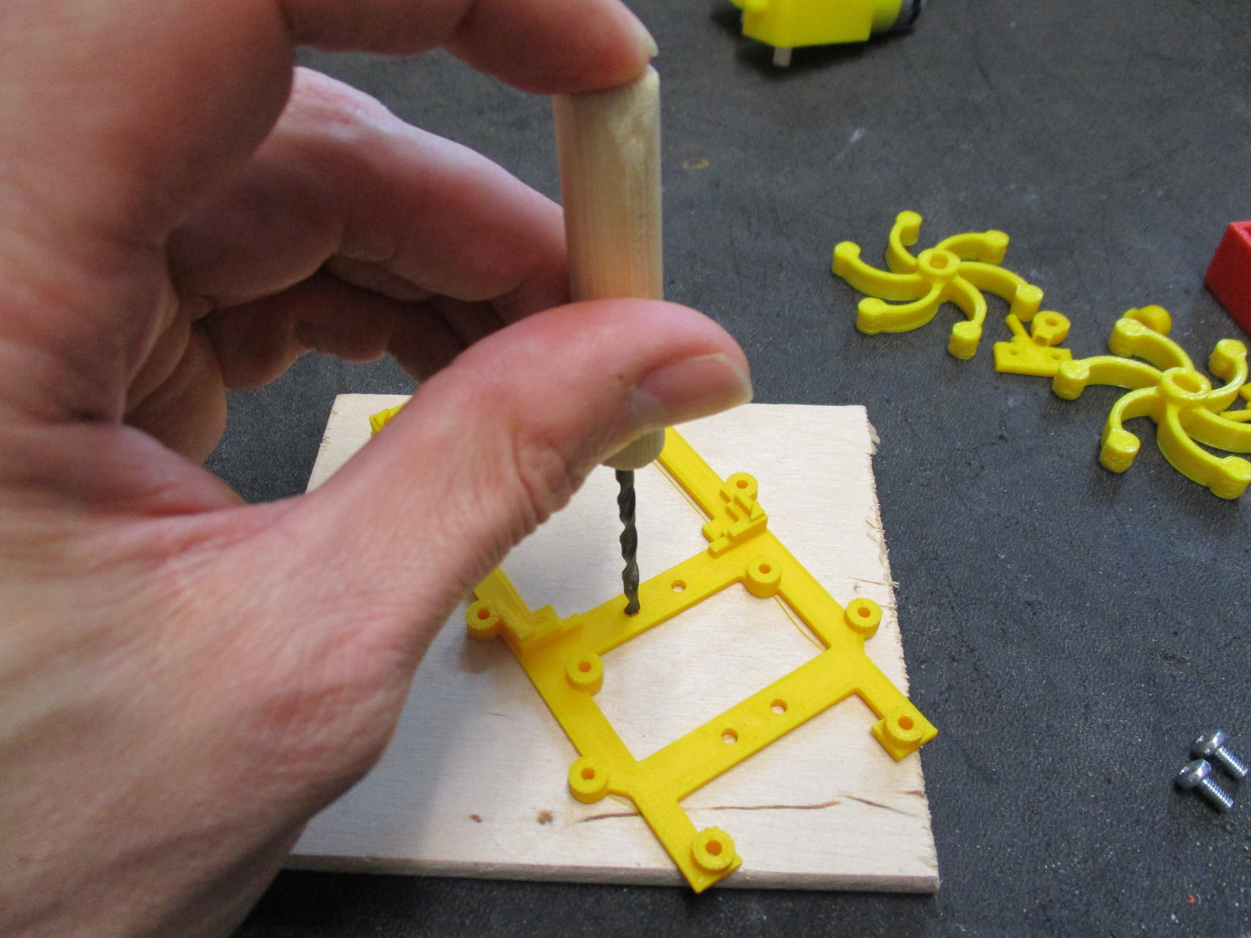
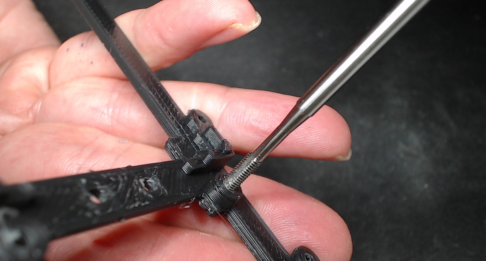
Figure 6 : drilling and tapping holes
Next assemble the chassis, motor bracket and battery clip as shown figure 7. IMPORTANT, make sure surfaces between the chassis, motor bracket and middle battery clip have ALL been filed flat, as these surfaces will be glued together using super glue. Test assemble the pieces using M3 x 6 bolts, making sure that these surfaces are parallel and flat. Note, super-glue is very good at gluing 3D printed PLA plastic, but the surfaces must be flat i.e. it will not fill any gaps / voids. IMPORTANT, do not over tighten the M3 bolts, its very easy to strip the threads. If all looks good disable the apply a SMALL amount of super glue on each contact surface between the battery clip, motor bracket and chassis. If surfaces are flat, you do need only a small amount of glue. Then bolt (pull) these together using the M3 bolts. Note, the middle bolts are only intended to provided enough clapping force whilst the glue sets, so do not over tighten. IMPORTANT, make sure that the chassis and motor bracket are square and the notch is facing forwards (see figure 8), before leaving the glue to dry, needs at least 10 minutes.
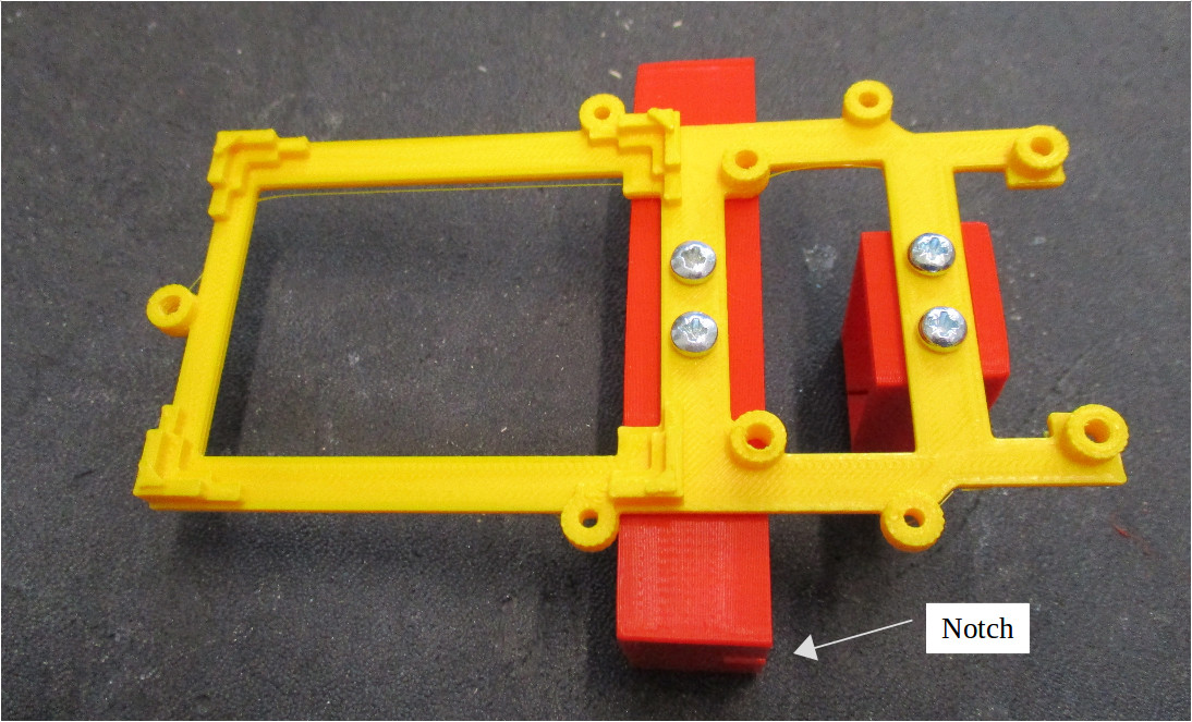
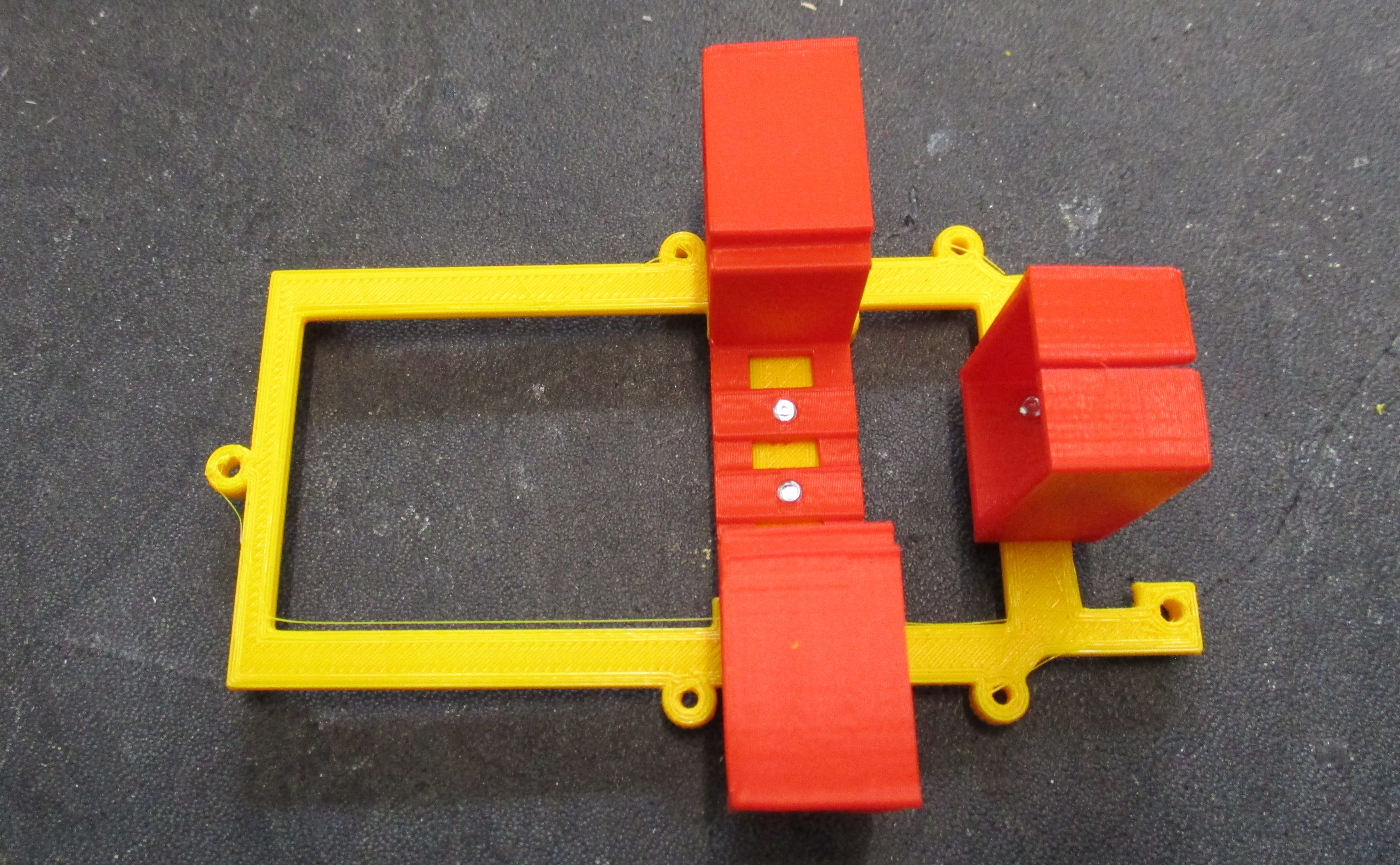
Figure 7 : assembling chassis
Insert each motor into the motor bracket as shown in figure 8, ensure each motor's mounting post slots into the recess and the the wheel "legs" face forwards. Then feed motor wires through the bracket towards the front of the robot.
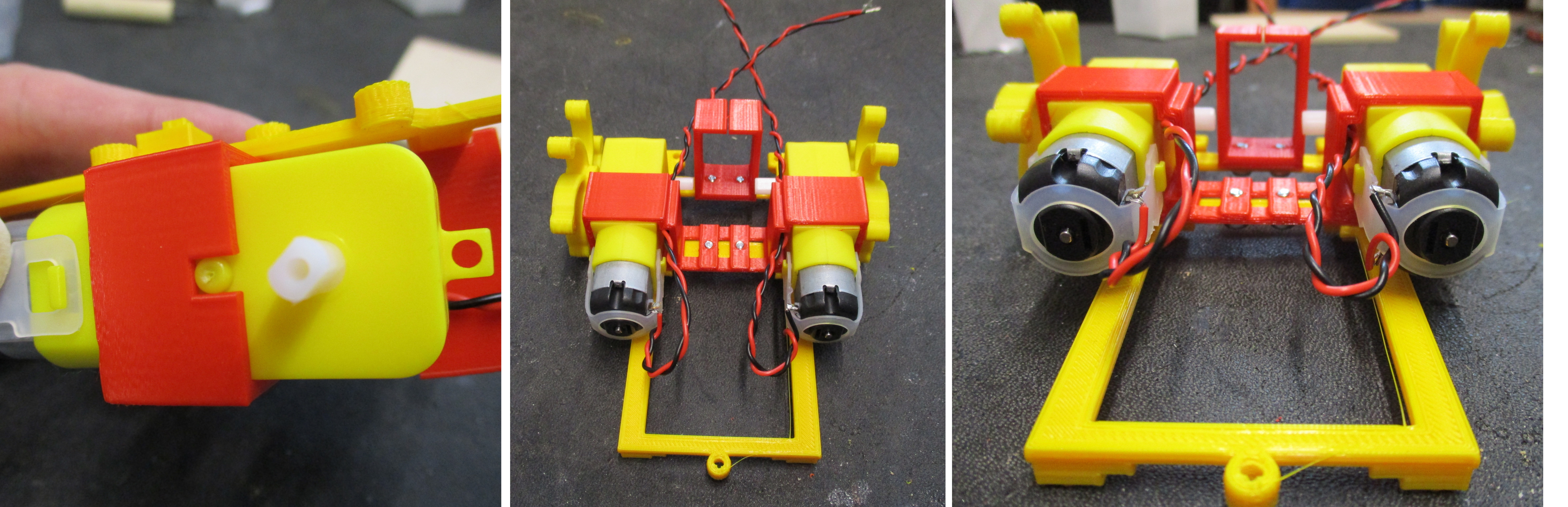
Figure 8 : mounting motors
File down any bumps on the spherical rear skid, then mix-up a small amount of 5min epoxy (a small pea size blob of epoxy and hardener), mix then fill the holes, insert the head of the M3x25 bolt and leave to set, as shown in figure 9. Note, alternatively hot-glue works fine.
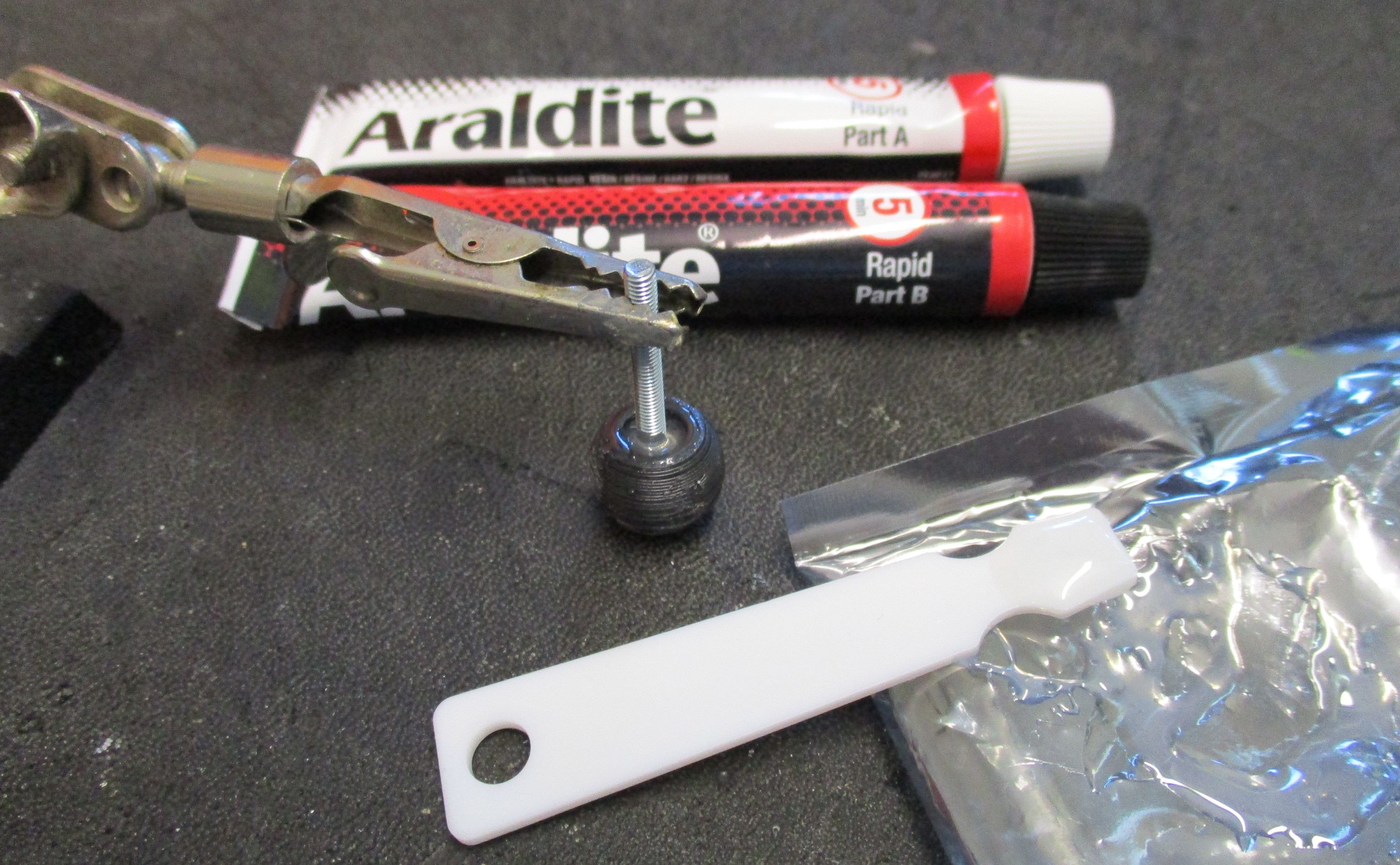
Figure 9 : rear skid
The front motor drive board is attached to the chassis using M3x6 and M3x15 bolts. The shorter 6mm long bolts secure the back to the board, the 15mm bolts the front. Note, the bumper sensor arms also mount onto the front 15mm bolts. The CPLD simply clips into the four corner posts. Next, screw the rear skid into the back mounting post and lock into position with an M3 nut, as shown in figure 10.
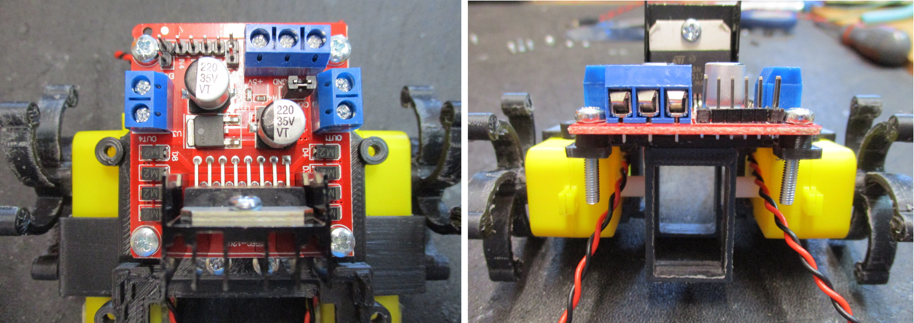
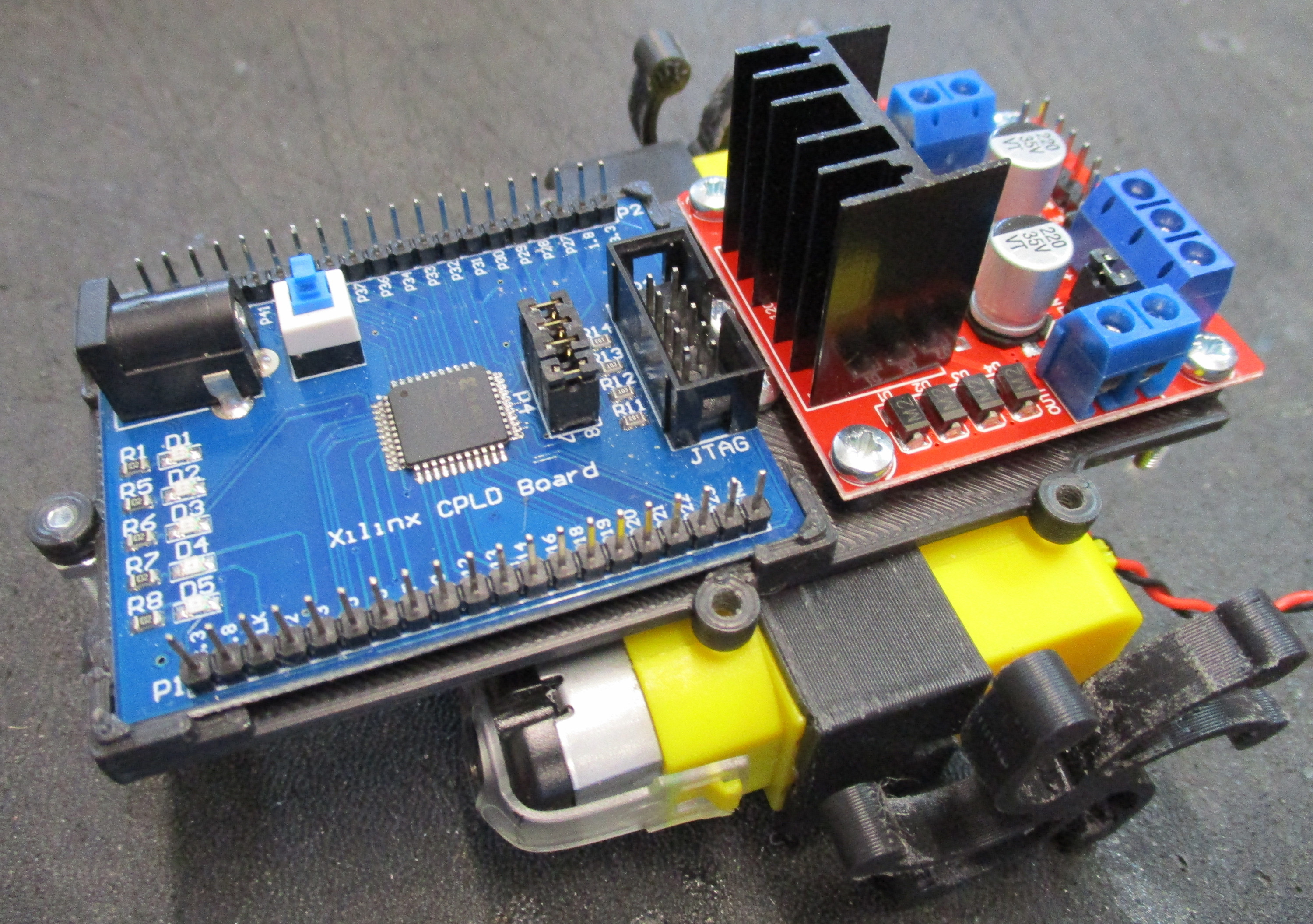
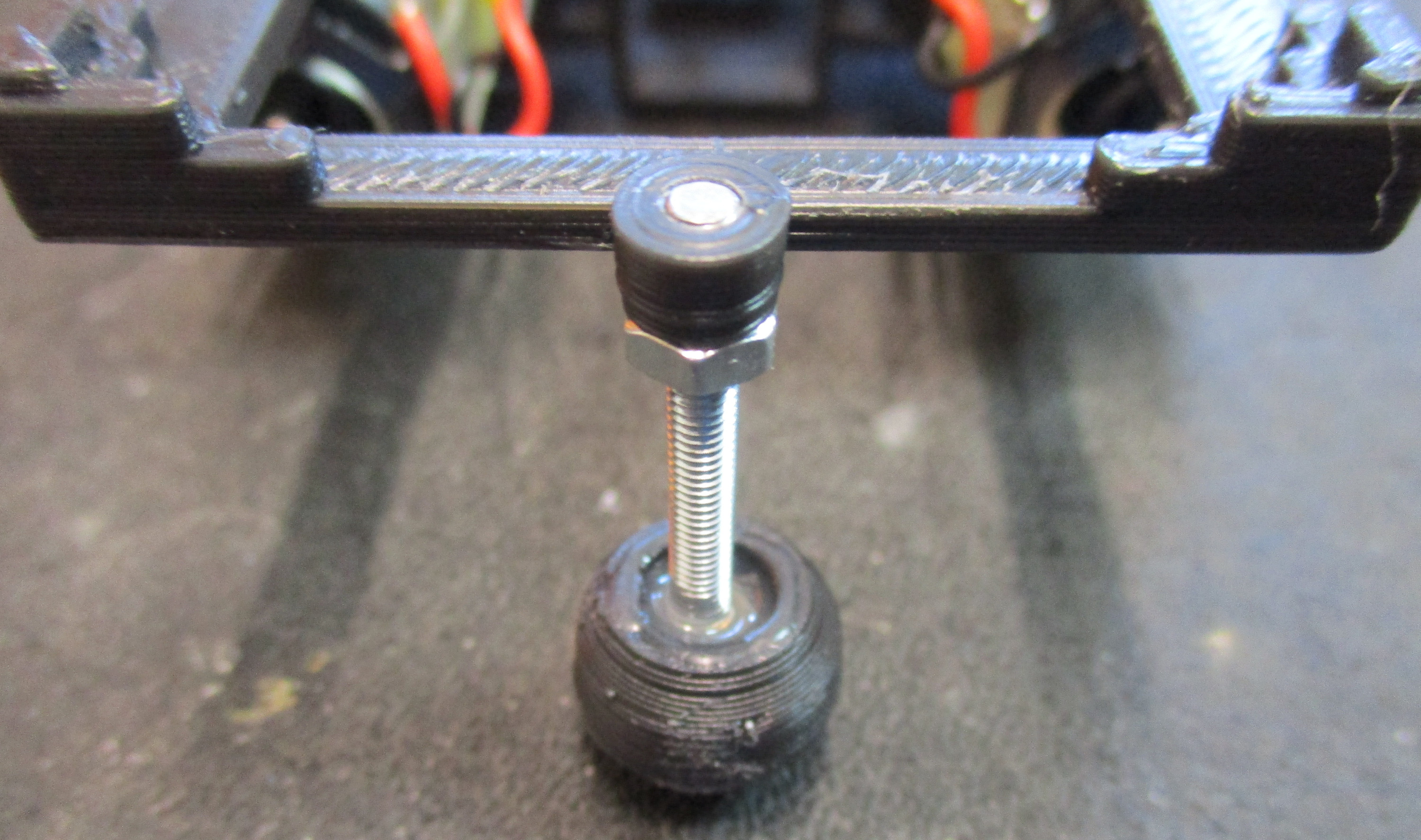
Figure 10 : attaching motor drive and CPLD boards
The main improvement to this version of the robo-cockroach is the replacement of the DIY wire switch, with micro-switches, as shown in figure 11. These are mounted a two-piece arm. If needed drill out the arm base using a M3 drill. Note, i found you did not need to do this one my ones. Test fit the two arm pieces, file flat where needed. Disassemble, place a small drop of super glue into the square hole, insert arm and allow to dry for 10 minutes. Note, if you have problems removing the arm, simply drip some glue down the side. Then attach the two micro-switches using the M2x12 bolts. M2 nut is optional. When assembled mount the arms on the front M3x15 bolts, ensure the micro-switch's wires are on the inside. This helps to guide the wires away from the wheels, as shown in figure 11. The arms can then be secured into position using a small drop of super glue, or using a star washer and M3 nut.
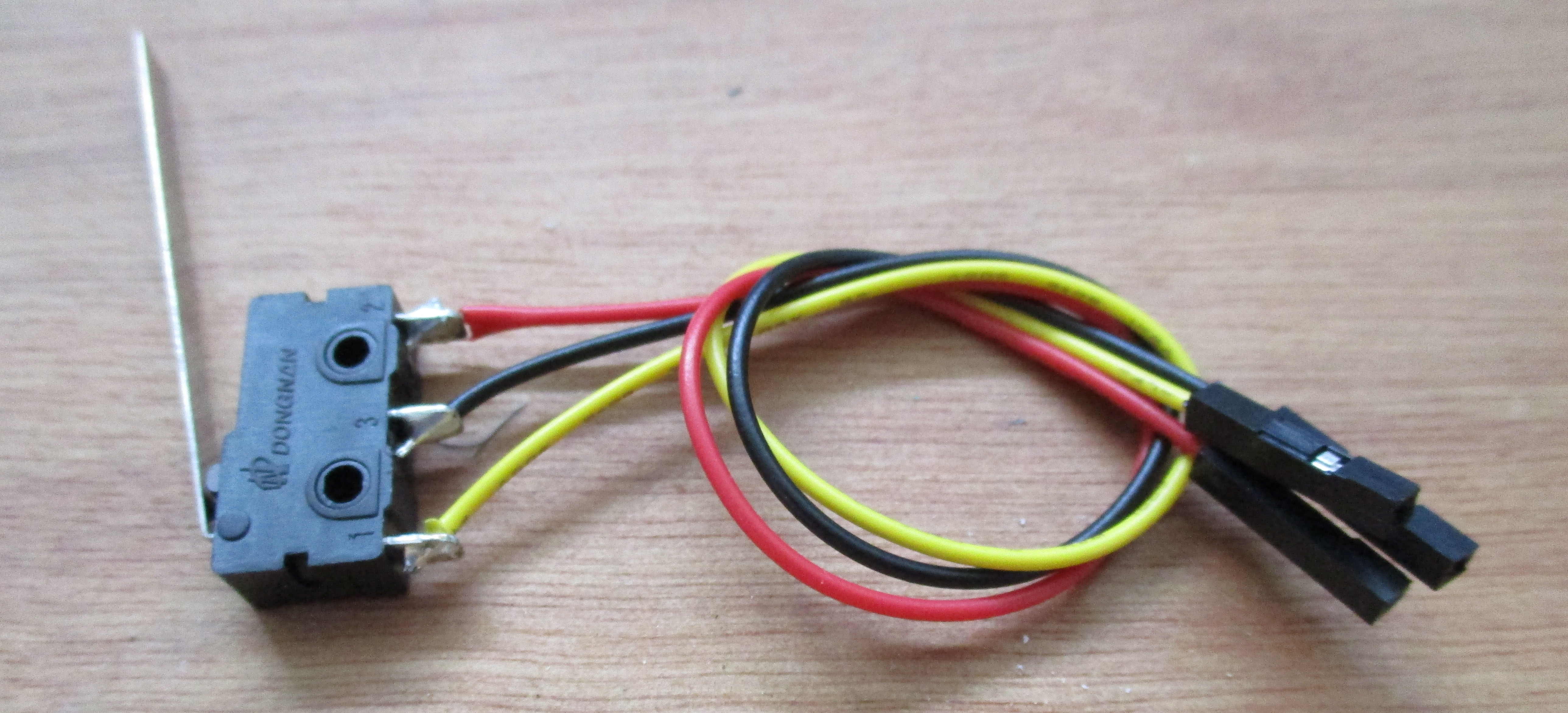
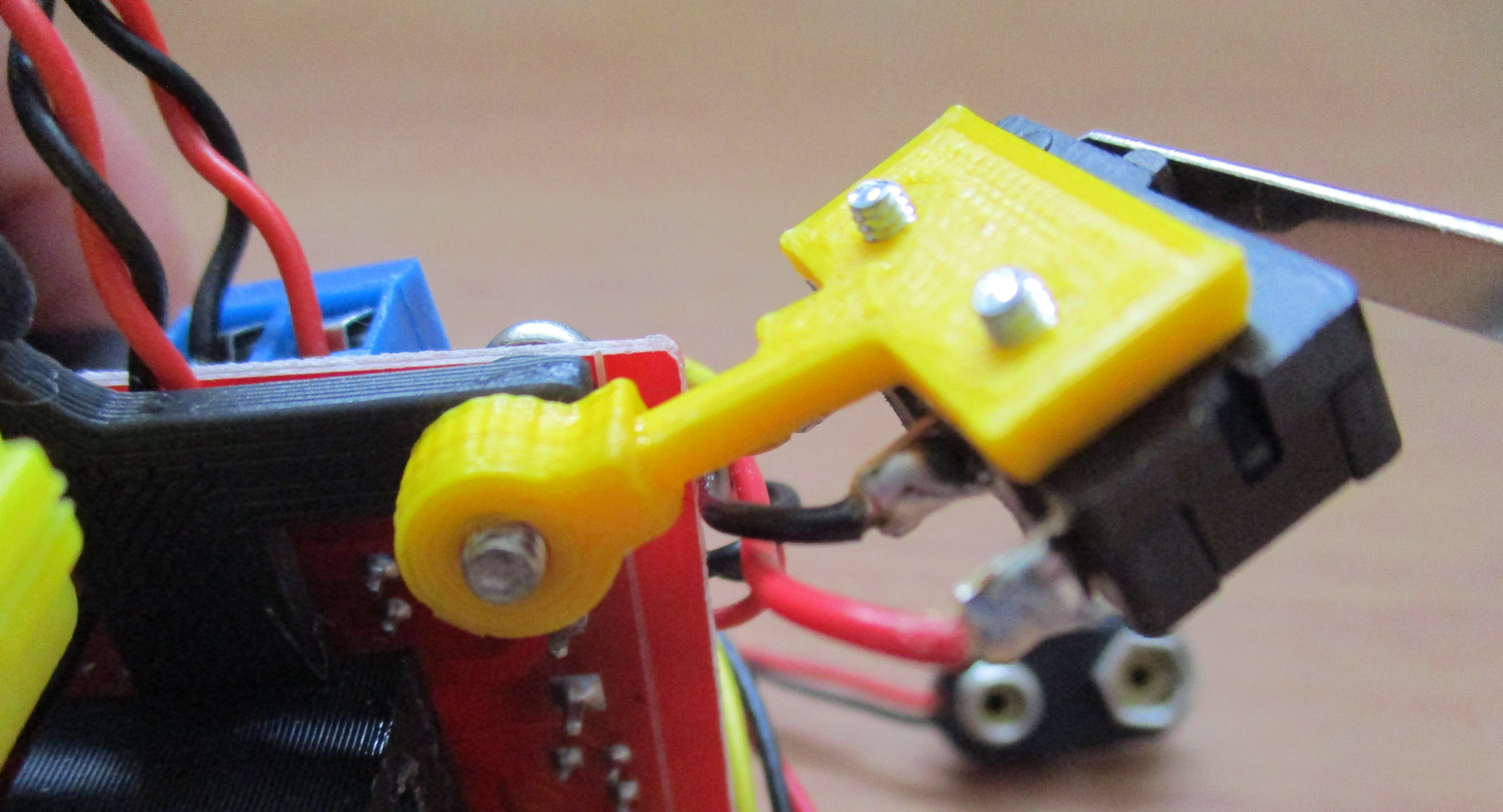
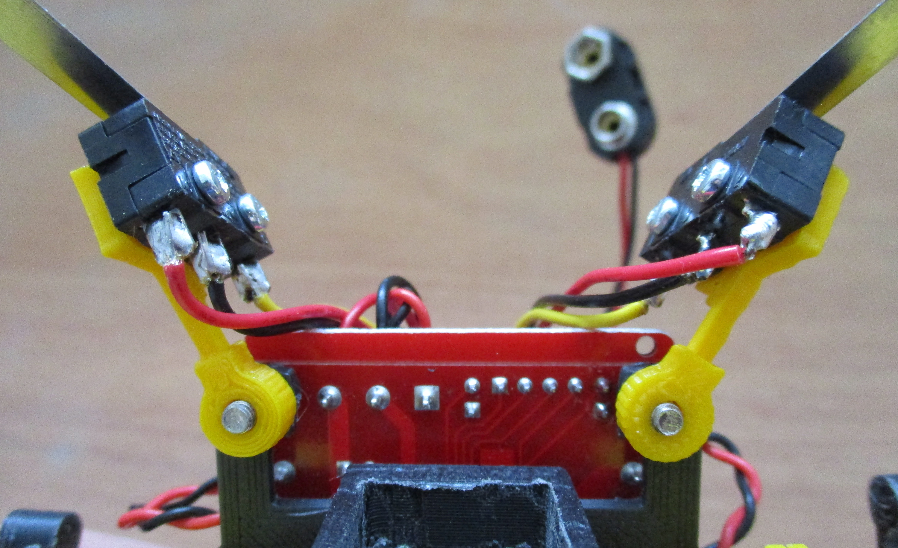
Figure 11 : bumper switch
Cut and strip the motor wires to length, strip off approximately 5mm of insulation to expose the copper wire, twist strands together and insert into motor controller board's side terminal blocks. The PP3 9V battery clip is wired into the front three-pin terminal block, as shown in figure 12. The 5V output is connected to the CPLD using a 2.1mm plug, wired using a 25cm twisted red and black, 7 strand wire (not single core), centre positive (+5V), outer negative (0V). Note, the all circuit share a common 0V line.
IMPORTANT: make sure the RED lead from the PP3 battery clip is wired into the +12V terminal, and the RED lead from the 2.1mm plug is wired into the +5V terminal. All black leads are wired to the 0V terminal. If you mix up the RED leads very bad things will happen. Unlike software you can only make a mistake once with hardware, once the magic smoke is released the hardware will not work again :).
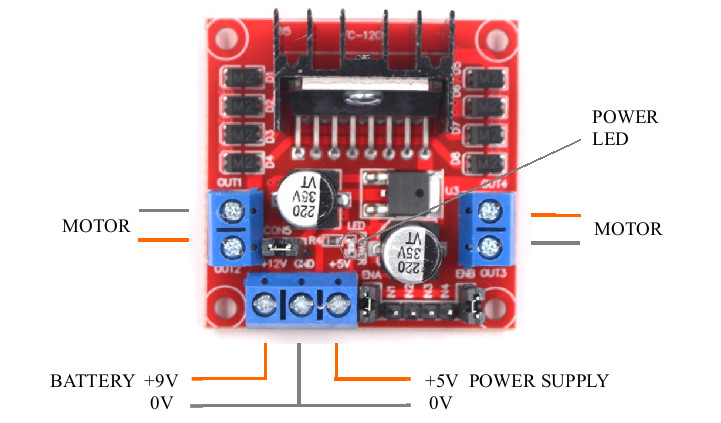
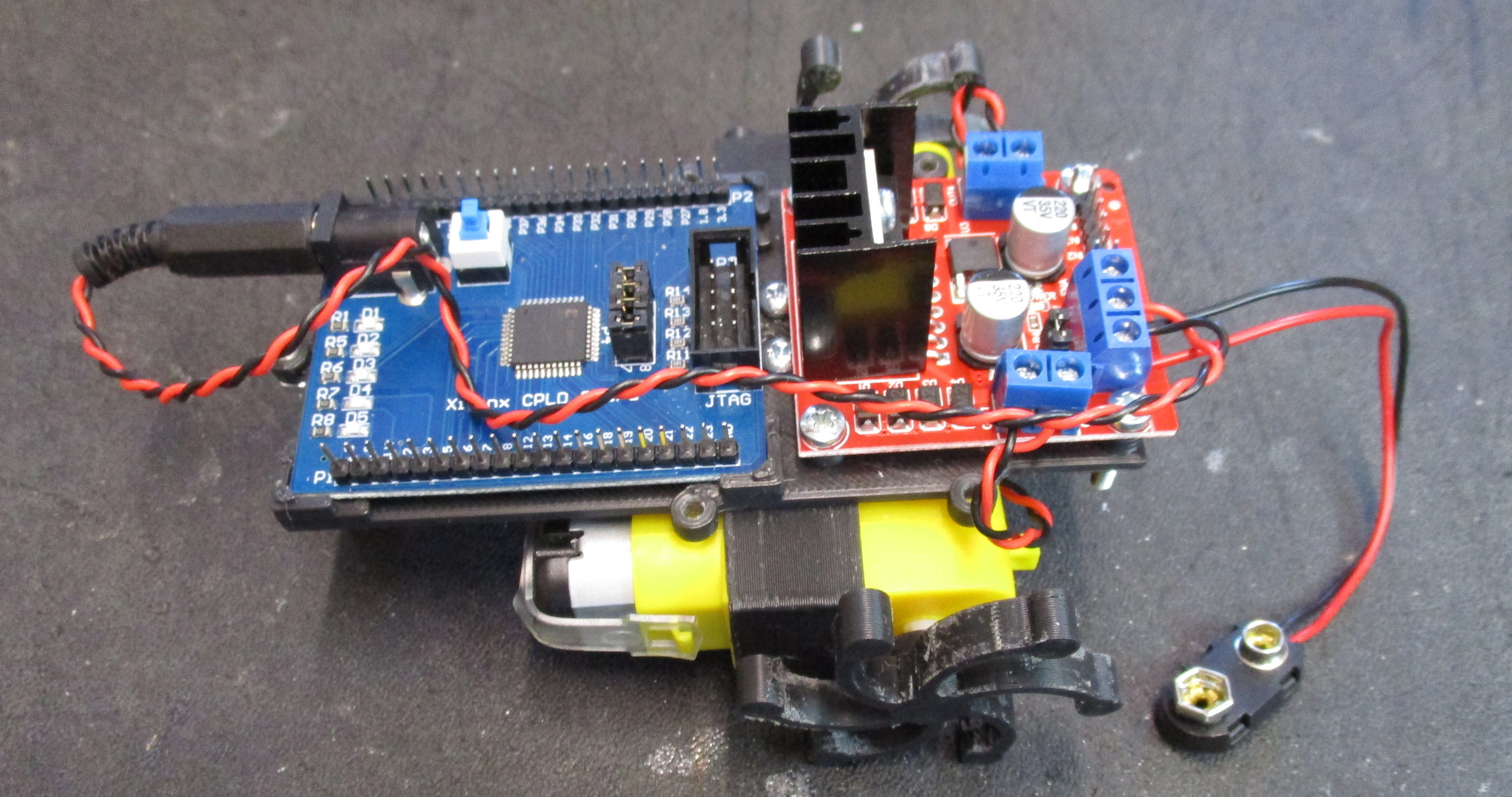
Figure 12 : wiring motor and power supply
The bumper sensor signals and motor control signals are attached to the CPLD board using female-female jumper leads as shown in figure 13. The motor control signals are wired as shown below i.e. the orange and yellow wires. Remove the ENA and ENB jumpers on the Hbridge board, these are the PWM control lines i.e. the green wires. There is also a purple reset wire connect between pins 42 and GND/3.3V. When this lead is connect to GND the robot will be held in a reset state (handy to prevent the robot moving off when being programmed). Moving the lead from pin GND to the 3.3V pin at the end of the edge connector will enable the robot. The the left and right micro-switches are connected as shown. IMPORTANT, make sure you do not mix up the micro-switch wires, as this may short out the power supply. Finally, insert the battery into the battery clip, but do not connect the battery connector yet.
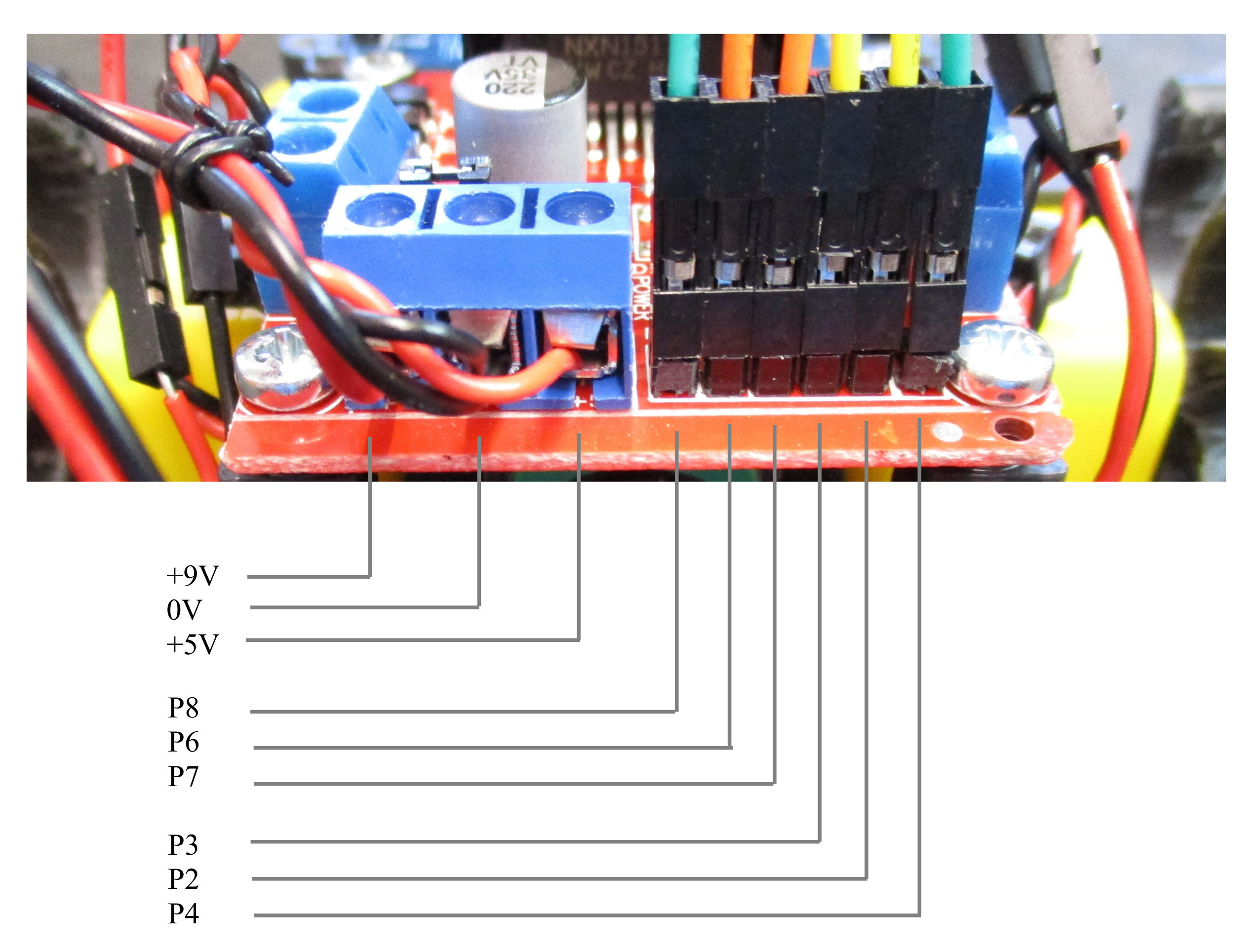
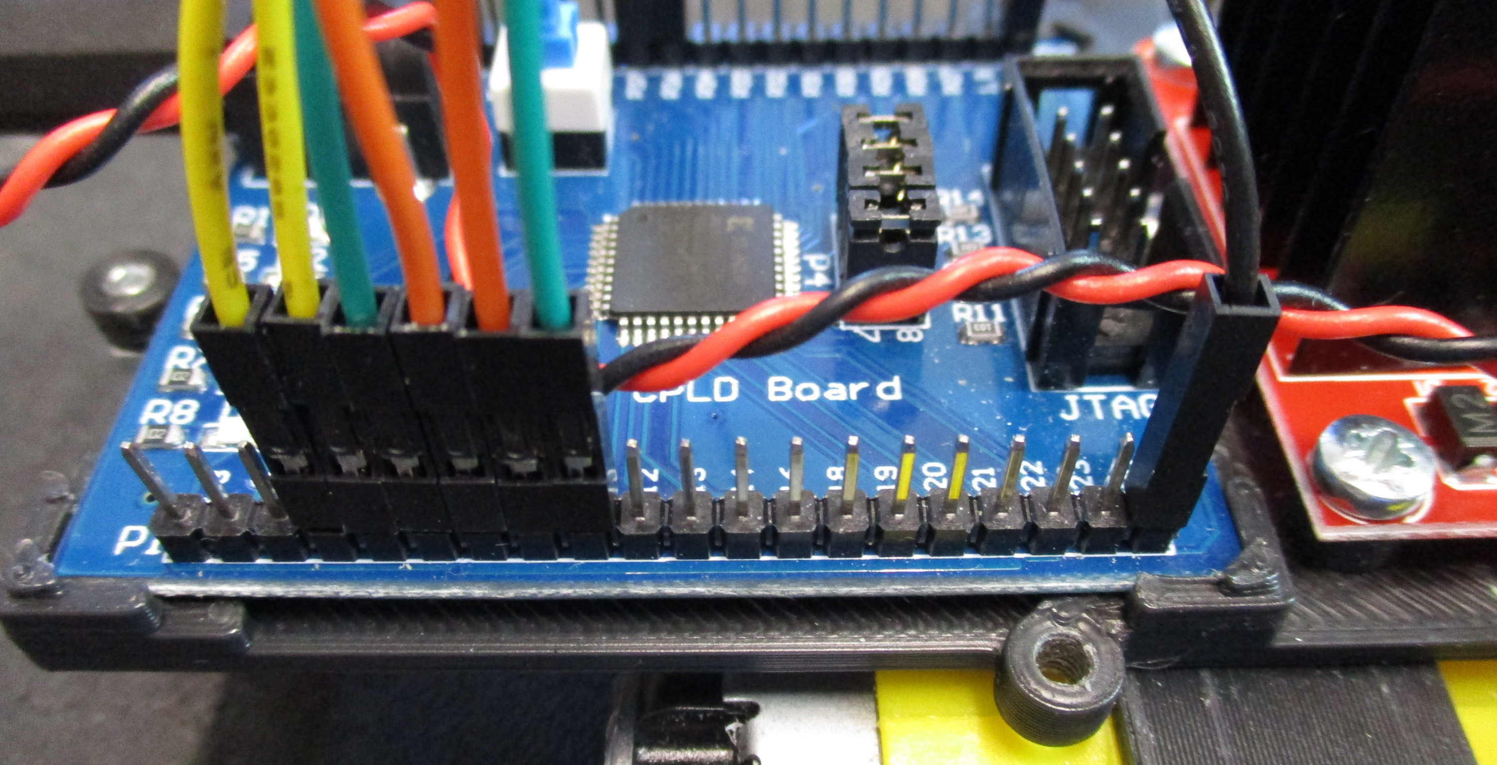
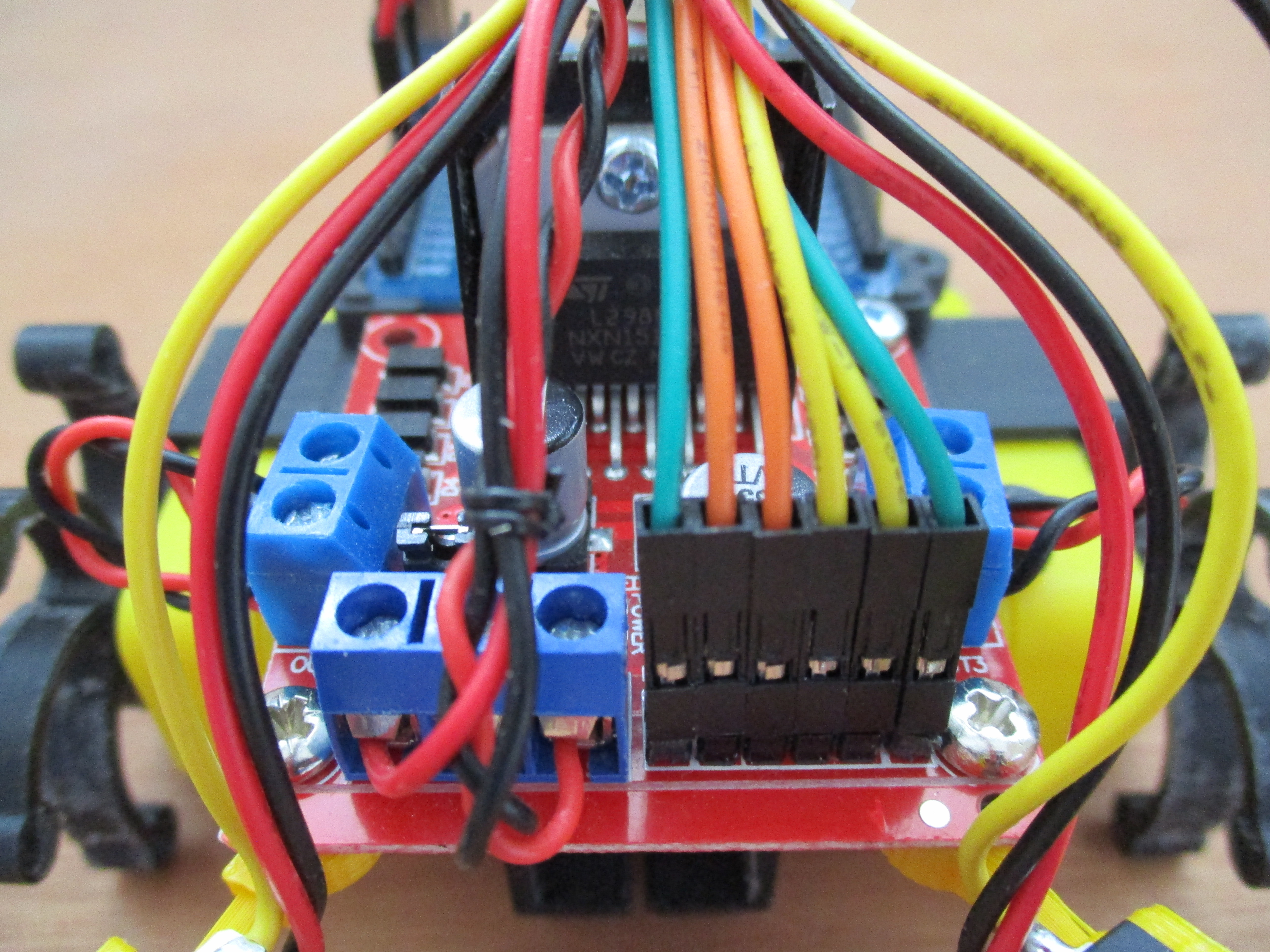
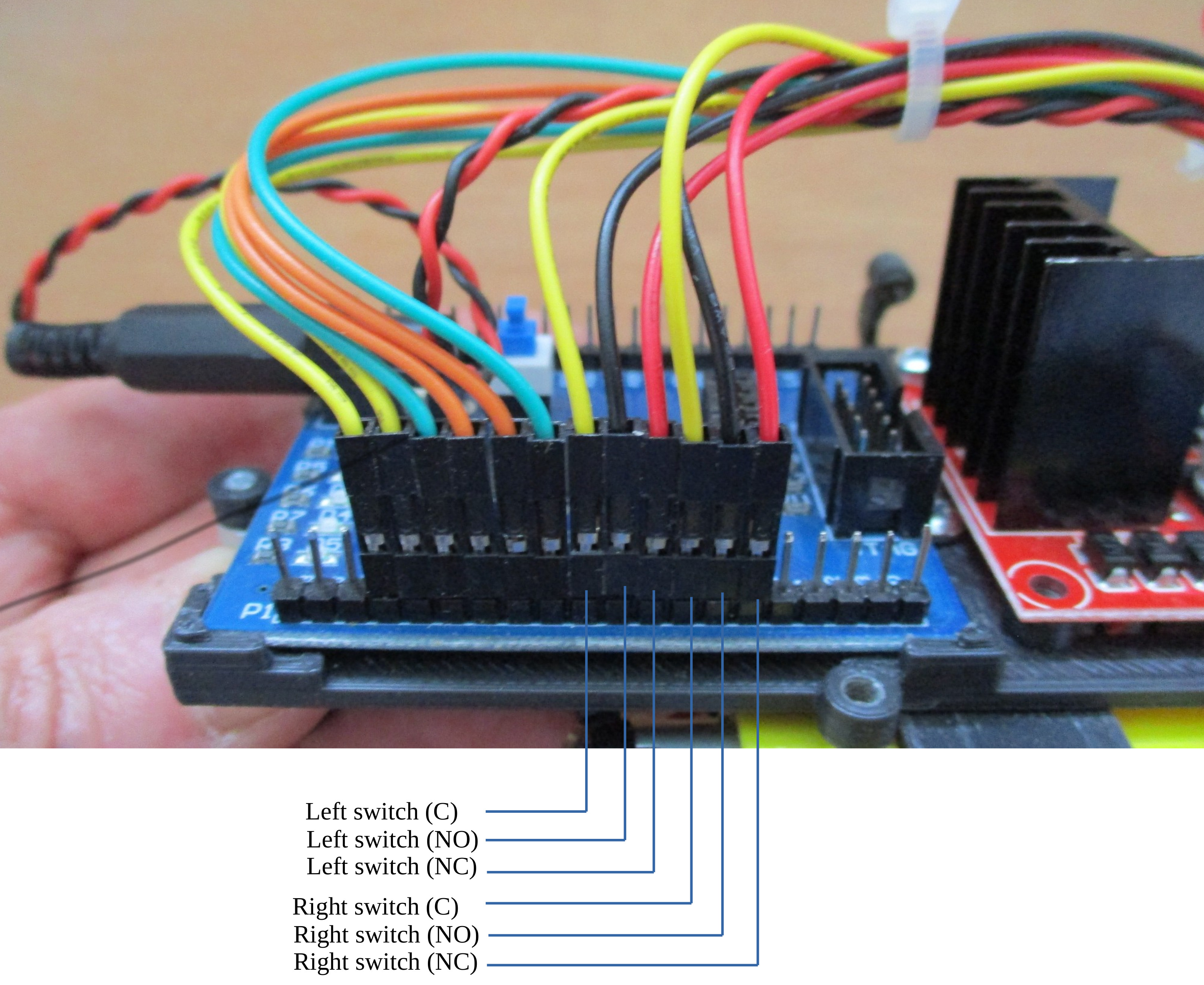
Figure 13 : wiring control signals
The first test before powering up any electronics is to give it a quick visual inspection to make sure you haven't done anything stupid e.g. i can't count the number of times ive plugged power cables in backwards, always check, check and check again. If all looks ok connect the PP3 battery, the LEDs on the motor controller and CPLD boards should turn on. If not disconnect immediately and check the battery and wiring. Note, you may need to press the CPLD power switch :)
If both LEDs turn on you can now use these Xilinx ISE projects to test the hardware. The following ISE projects use the onboard 50MHz oscillator to test out the robots basic functionality:
Test 0 : unzip test0.zip and open the ISE project, double click on Manage Configuration (Impact) to generate the .jed file and open the programming software, as shown in figure 14. Connect the robot to the USB programming cable, turn on the robot's power, you should see the programming cables status LEDs turn blue. If one LED is red this normally means that the robot is not powered / connected correctly. In the impact window double click on the Boundary scan option, then right click in the new boundary scan tab selecting initialise chain. The CPLD icon should appear, right click on this icon selecting Program, confirm default configuration and click OK. If all has gone well a blue programming complete message should be displayed. Note, to start you robot move the reset lead from GND to the 3.3V pin, or just unplug\remove the purple reset lead.
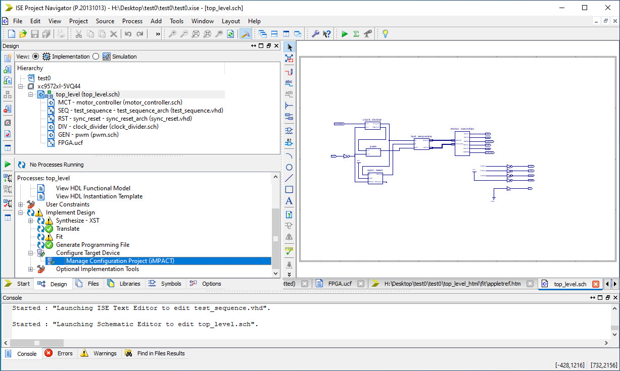
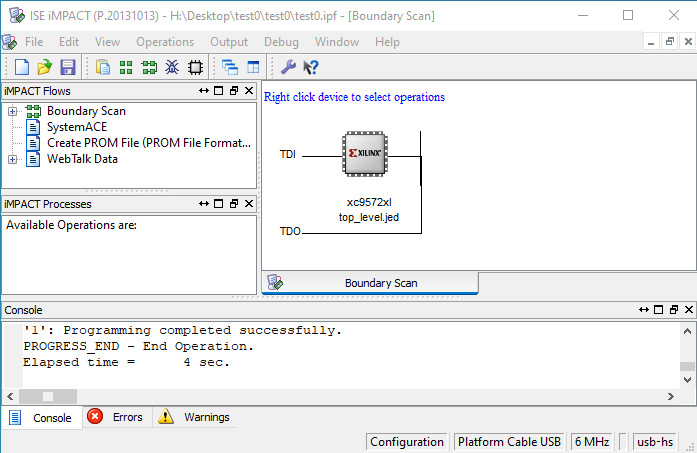
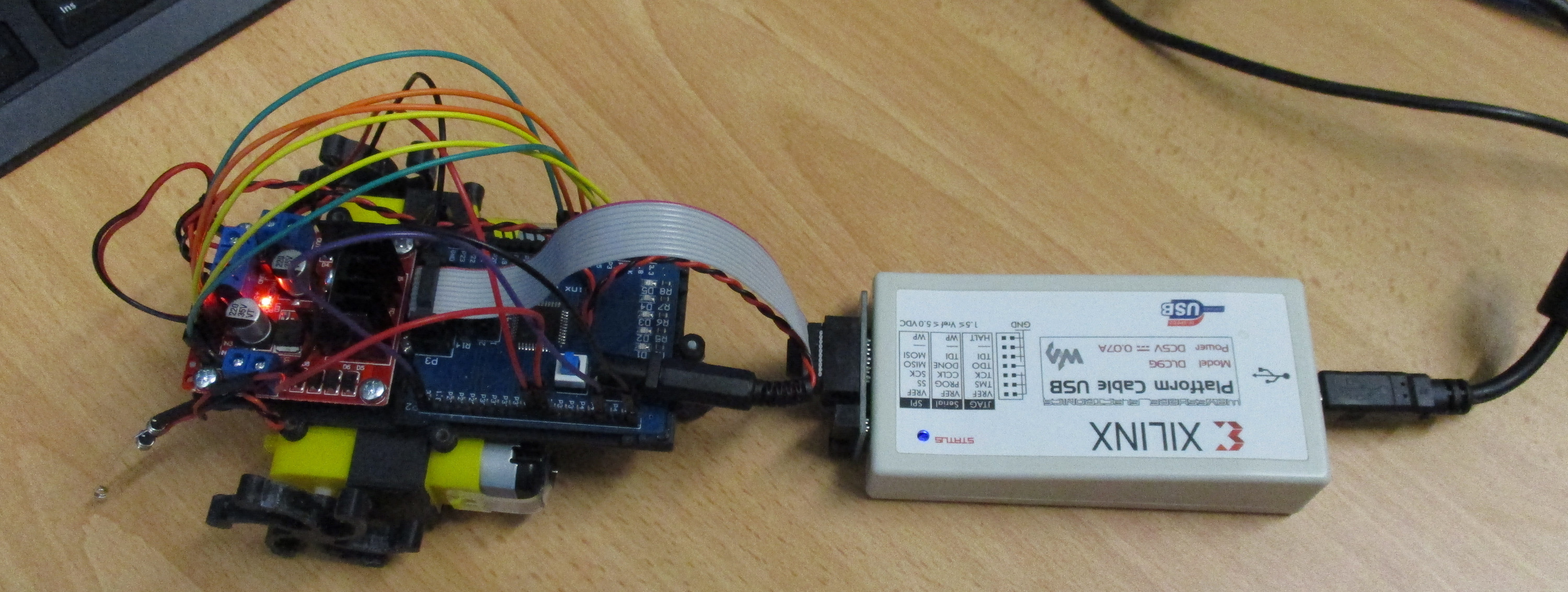
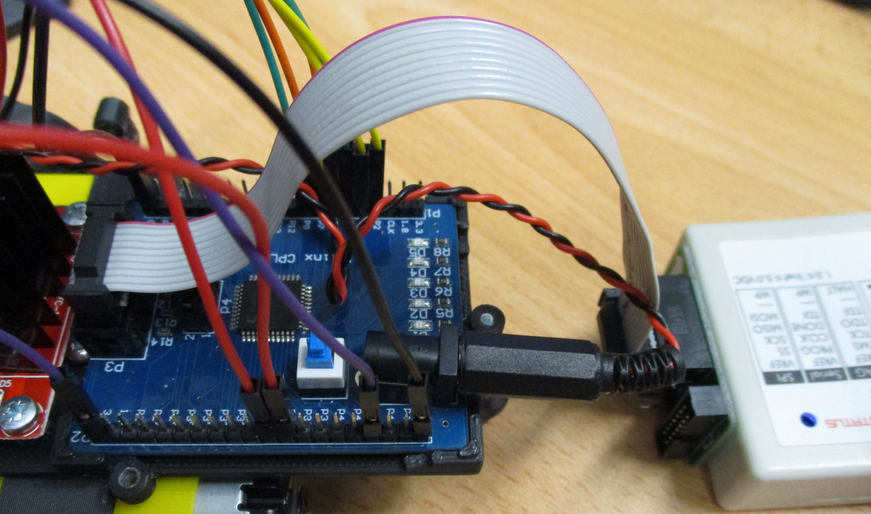
Figure 14 : configuring CPLD
This simple state machine generates a sequence of movement commands below. A short video of the robot in action is available here:(Link)
If the wheels do not rotate, check that both boards are getting power, using a multimeter check that you are getting 9V from the battery and +5V from the regulator, these can be measured from the front three-pin terminal block. If power is good, but no movement check wiring. Note, disconnect battery when you are doing this. If the wheels are not rotating in the correct directions i.e. the robot performs different movements to the video, then one or both motors have been wired in backwards. This can be corrected by swapping over the leads in the motor terminal blocks. If the robot repeatedly moves forwards and then stops, then the PP3 may not have enough power to power the robot i.e. the CPLD voltage is not stable. To fix this a new battery is the best solution, but you can also try adding a smoothing capacitor between the 0V and +5V power rails, as shown in figure 15.
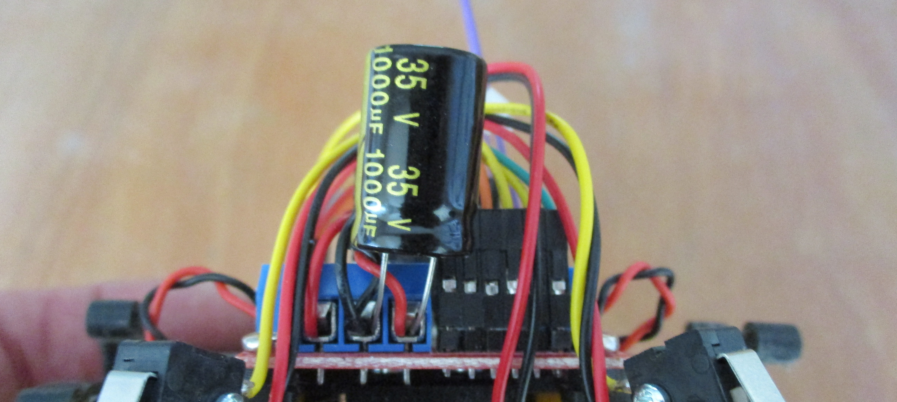
Figure 15 : adding a smoothing capacitor
Test 0a : simple state machine generates a sequence of movement commands to drive a square. A short video of the robot in action is available here:(Link)
The intention of this test code is to calibrate the open loop control such that the robot performs a perfect square, well that was the intention, however, you soon find out that you get a lot of wheel spin with legged wheels and overshoot, so you will never get that perfect square without some adjustments to the control algorithms / hardware used :). However, you can make small adjustments to the PWM and system clock i.e. adding stages to the ring counter to slow down the PWM, slowing down the system clock.
Test 1 : explore and avoid obstacle behaviours as previously designed. A short video of the robot in action is available here:(Link). Now when the robot hits an obstacle it will reverse, turn and then move in the opposite direction.
WORK IN PROGRESS

This work is licensed under a Creative Commons Attribution-NonCommercial-NoDerivatives 4.0 International License.
Contact email: mike@simplecpudesign.com