Once you have built your processor its tempting to simply hand-code the machine code i.e. write out the raw 1's and 0's for each instruction. This may sound painful, but you do get your eye in, you start to see the matrix :). Combined with a bit of cut and paste, you can get by taking this approach. However, after a while, especially if your coming back to programs you wrote a little while ago, you start to have toooo much fun and you need an a basic assembler to make your life a little easier. Therefore, rule number one of programming: you can only write so much machine code before you write an assembler :).
Note, the latest version of the simpleCPUv1a and simpleCPUv1d assembler can be found here: (Link).
Input file format
Output file formats
Python assembler - version 1.0
M4 pre-processor
Python assembler - version 1.1
Python assembler - version 1.2
Python assembler - version 1.3
Python assembler - version 1.4
Python assembler - version 2
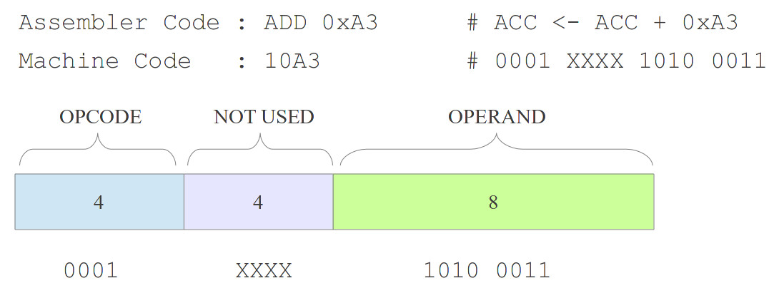
If you Google the word "assembler" you get: "a program for converting instructions written in low-level symbolic code into machine code" which is pretty much on the money. At their hearts assemblers are very simple pieces of software converting the assembly language mnemonics we can read into the binary 1's and 0s that are the machine code that the processor speaks. Note, remember there is a one-to-one mapping between assembler and machine code i.e. one line of assembler = one machine code instruction, unlike a high level language like C, were one line of C could equal hundreds of lines of assembler (or more). The aim of this assembler is a basic, no frills piece of software, programmed in Python, to simplify code development, converting text into numbers as shown in figure 1.
Figure 1 : the assembly process, Assembly code (top), 1's and 0s (bottom)
Note, real world assemblers also need a little bit of optimisation and extra house keeping functionality to allow them to be practical, which we will discuss at the end, but not the main aim of this cheap and cheerful assembler.
From a historical perspective assemblers are defined a by the number of times they read the assembler source file i.e. a 1-pass or a 2-pass design. Note, i guess now days we would say one pass or multiple pass assemblers. I think this original distinction was due to how data was stored in these old machines i.e. tape. Rewinding these tapes to read a file again takes time, so back then multiple pass assemblers were not time efficient. An example of the joys of tape is available here: (Video). I confess do like these old machines, real computers: mechanically large, with lots of lights and sounds :). Back to assemblers, the main differences between these two approaches (1 or 2 pass) was how do you handle forward references e.g. JUMP exit. The label "exit" is the address of an instruction further ahead in the program, the first time the assembler reads through a program the address of this label is unknown. For 1-pass assemblers, this address must be resolved later, for 2-pass this is calculated on a previous pass. For more info on these differences refer to : (Link). Whatever approach is taken you still need to produce the same result i.e. the program's machine code. This assembler is going to be very simple, so it doesn't quite fit into your traditional definitions. You could say its a one pass, but that's not quite correct as ive chopped out a lot of the functionality e.g. labels are not supported in this initial version.
Initially to avoid the whole forward reference problem i decided to pass this problem over to the programmer i.e. make it a manual two pass process, where the programmer identifies the addresses of the instructions, manually updates the source code with the correct addresses and then re-runs the assembler. Combined with the M4 macro pre-processor (discussed later) this produced a workable solutions for the types of program used on these types of simpleCPU v1a based systems (Link).
Note, the aim of this assembler is to demonstrate the mechanics of converting assembly code into machine code, it is not intended to be a fully functional assembler. The identified deficiencies of this assembler are "fixed" in later implementations.
The source code format is stored as an ASCII file, an example is shown below:
#
# TEST PROGRAM
#

move 0x00

add 1
jumpNZ 1
jump 0
Comments are indicated using the '#' character, empty lines are passed unaltered. Lines starting with a character are considered instructions, constants can be used represented in hexadecimal (leading 0x) or decimal. Data values are limited to the range: 0-255. The simpleCPU uses a fixed length instruction format i.e. each instruction is represented using 16bits, stored in one memory location. In the above example the addresses used by the JUMP instructions are easy to manually enter as the boot/reset vector i.e. the address of the first instruction on power-up, is known to be address 0 and each instruction takes one address/location. However, for larger programs manually counting lines will become a bit more tricky, therefore, the assembler dumps out an intermediate file in which it calculates each instruction's memory address, as shown below:
#
# TEST PROGRAM
#

000 move    0x00

001 add     1
002 jumpNZ  1
003 jump    0
The user can scan through this file, identify the addresses of the branch targets and update the original source text files accordingly i.e. replace the original place holder / dummy values, just as a 2-pass assembler would do. Note, this new address field is a decimal value, varying from 0 - 255. This file is then converted into the raw machine code used to program the computer:
0000 0000 1001 A001 8000
This first value is the starting address (0000), followed by four hexadecimal (16bit) values, each representing one of the original instructions e.g. move 0x00 is mapped to the bit pattern 0000, add 1 to 1001 etc.
Before we can write the assembler we also need to know what the required output file formats are. For the simpleCPU v1a, this comes in two flavours: 8bit to program the two EPROMs used in the bread-board version, and 16bit to program the FPGA version. To program the EPROMs i used is BK Precvision 844USB, as shown in figure 2.
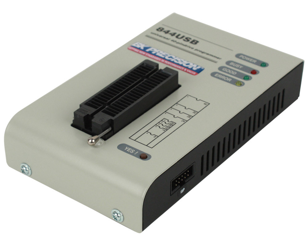
Figure 2 : programmer
This programmer supports two simple ASCII HEX formats (descriptions taken from help menu):
Each data byte is represented as 2 hexadecimal characters, and is separated with a white space from following data bytes. The address for data bytes is set by using a sequence of $Annnn, characters, where nnnn is the 4-hex characters of the address. The comma is required. Although each data byte has an address, most are implied. Data bytes are addressed sequentially unless an explicit address is included in the data stream. Implicitly, the file starts an address 0 if no address is set before the first data byte. The file begins with a STX (Control-B) character (0x02) and ends with a ET (Control-C) character (0x03). Note: The checksum field consists of 4 hex characters between the $S and comma characters. The checksum immediately follows an end code.
Here is an example of ASCII HEX file. It contains the data "Hello, World" to be loaded at address 0x1000:
^B $A1000,
48 65 6C 6C 6F 2C 20 57 6F 72 6C 64 0A ^C
$S0452,
A very simple hex file format similar as ASCII HEX without checksum field, without start (STX) and end (ETX) characters. Each data byte is represented as 2 hexadecimal characters, and is separated with a white space from other data bytes. The address field is also separated by white space from data bytes. The address is set by using a sequence of 4-8 hex characters.
Here is an example of ASCII SPACE file. It contains the data "Hello, World" to be loaded at address 0x1000:
0001000 48 65 6C 6C 6F 2C 20 57 6F 72 6C 64 0A
I decided to keep it simple and went for the ASCII SPACE format. This output will be used to program the two 2764 8bit EPROMs (Link). Therefore, the assembler will generate two output files: representing the low byte and high byte of the 16bit instruction. The FPGA version of this processor is implemented on an Xilinx FPGA so need to use Xilinx specific output files:
This file format is used to initialise CORE-gen memory ip blocks (Link). An example is shown below, basically a small header block defining the number based used, comma separated values, followed by the memory contents. Note, assumes you start at address 0 i.e. no address field. This file is only read during the synthesis stage, therefore, if this file is updated the complete design will need to be re-synthesised even if the processor's hardware has not been modified, otherwise the FPGA configuration bit file will not be updated. This can be a bit of a pain when developing / testing software as repeatedly re-synthesising and the associated place-and-route phase can take a significant amount of time.
memory_initialization_radix = 16;
memory_initialization_vector =
0001, 4100, 4510, 8003, 0000, 0000, 0000, 0000,
0000, 0000, 0000, 0000, 0000, 0000, 0000, 0000,
To get around the problem of re-synthesising the processor each time the software is updated, Xilinx provides the data2mem tool. This allows you to update the contents of a memory component (BlockRAM), within a bit file i.e. the FPGA configuration file, without having to go through the re-synthesise process. The data2mem tools use the .mem file format, as described in the data2mem user guide (Link). An example is shown below, a simple format, defining the start address using the '@' character, then a list of numbers defined as hexadecimal values. Note, this file format uses a reversed nibble representation i.e. least significant data nibble first (data is reversed when compared to the previous format).
@00000000
1000 0014 0154 3008 0000 0000 0000 0000
0000 0000 0000 0000 0000 0000 0000 0000
The final format that ive used in the past is a raw ASCII binary format. Note, not sure if this evolved from stuff i was doing or if its an actual format, anyway i use this format to configure VHDL RAM models for simulations. Each line defines one memory location's binary value, specifying the address as a decimal value and the data as a binary string :
0014 0000000000000010
0015 0000000000000001
0016 0001000011111111
In this example the first line defines address 14, and the data value 2 i.e. the instruction move 0x02, address and data are separated by a single space. Addresses can be in any order i.e. do not need to be sequential as in this example.
To simplify hardware construction this version of the processor only has a very limited instruction set:
In this instruction syntax X=Not-used, K=Constant and A=Address. The complexity of an instruction is also defined by its addressing mode i.e. not just how much number crunching it does, but how it fetches its operands (data). Again, to simplify the required hardware these instructions are limited to simple addressing modes:
Note, i reverted back to the more traditional use of LOAD and STORE, rather than INPUT and OUTPUT for this version of the processor i.e. instructions that read and write to memory i.e. LOAD=INPUT=READ, STORE=OUTPUT=WRITE.
As shown in the above table, bits (11 downto 8) i.e. the lower nibble of the high byte, are not used by the CPU (marked XXXX). These four bits could be removed to reduce the 16bit instruction down to a 12bit instruction. However, as memory ICs used in the bread-board implementation are 8bit, we don't reduce IC count going to 12bit. Therefore, i stuck with 16bits as it allows for possible future instruction set expansion. For FPGA implementations it would make a difference as the hardware design can be reconfigured to match the new smaller instruction format, however, to keep things simple going to standardise on a fixed 16bit instruction format.
Version 1.0: the heart of this simple assembler is shown below, to see it in its full glory you can also download the assembler here: (Link). The core of this program simply reads the ASCII text file containing the assembly language program into a list. It then matches and replaces the assembly language instructions with their hexadecimal values. Input text files are given the extension .asm, output ASCII files the extension .asc. This initial implementation generates the EPROM programming files, with output data split across two files. The user passes the output file "name", this name is extended to "high_name" and "low_name" for the high and low EPROMs. At this time the FPGA files are not generated, but the program does generate a combined 16bit version "name.asc", i will update the FPGA side for version 2. The basic usage is:
Usage: simpleCPUv1a_as.py -i <input_file.asm> -o <output_file> -a <address_offset> -t <input_file_type>

./simpleCPUv1a_as.py -i test -o test
File extensions are automatically added by the program. The default start address is 0x00, but this can be altered using the -a option. This is handy when you are generating code for a shared ROM i.e. the bread-boarded implementation can store up to eight programs in its EPROM, each is aligned on a 256 byte page. You can also assemble a pre-processed file i.e. a file where the address field has been added (as discussed in the above input file format sections). This is sometimes useful, you can rename the auto generated intermediate tmp.asm file and continue to add instructions with their addresses. Also wrote a program to auto renumber these addresses if you lost count, or cut and pasted in blocks of code with the wrong address fields. This extra program can be downloaded here: (Link).
    while True:
      line = tmp_file.readline()
      if line == '':
        break

      if line[0] =='\r' or line[0] =='\n' or line[0] =='#' or line[0] ==' ':
        pass
      else:
        text = re.sub(' +', ' ', line.lower())
        words = text.split(' ')

        opcode = ''
        operand = ''

        if words[0].isdigit():

          # match opcode #
          if words[1]   == "move":
            opcode = "00 "
          elif words[1] == "add":
            opcode = "10 "
          elif words[1] == "sub":
            opcode = "20 "
          elif words[1] == "and":
            opcode = "30 "
          elif words[1] == "load":
            opcode = "40 "
          elif words[1] == "store":
            opcode = "50 "
          elif words[1] == "jump":
            opcode = "80 "
          elif words[1] == "jumpu":
            opcode = "80 "
          elif words[1] == "jumpz":
            opcode = "90 "
          elif words[1] == "jumpnz":
            opcode = "A0 "
          else:
            print "Error: invalid opcode"
            print words
            return

          if len(words) >= 2:
            data = words[2].rstrip()
            if '0x' not in data:
              if int(data) < 256:
                operand = str.format('{:02X}', int(data)) + ' '
              else:
                print "Error: invalid operand"
                print words
                return
            else:
              if len(data) == 4:
                operand = data[2:4] + ' '
              elif len(tmp) == 3:
                operand = "0" + data[2] + ' '
              else:
                print "Error: invalid operand"
                print words
                return
          else:
            print "Error: invalid operand"
            print words
            return

        # if opcode and operand good write instruction #
        print opcode, operand
        if opcode == '' or operand == '':
          print "Error: invalid instruction"
          print words
          return

        else:
          instruction_count += 1

          # update EPROM files #
          high_byte_file.write(opcode)
          low_byte_file.write(operand)
          word_file.write(opcode.strip() + operand)


          byte_count += 1
          if byte_count == 16:
            byte_count = 0
            high_byte_file.write("\n")
            low_byte_file.write("\n")
            word_file.write("\n")

            instruction_address += 16
            addressString = str.format('{:04X}', instruction_address) + ' '
            high_byte_file.write(addressString)
            low_byte_file.write(addressString)
            word_file.write(addressString)
To test this assembler the bread-boarded test program described here: (Link) was used as the source file: (testCode.asm). The output files generated are shown below:
#HIGH BYTE
0000 00 00 00 00 00 00 00 00 00 00 00 00 00 00 00 00
0010 10 10 10 10 20 20 20 20 20 10 20 10 20 10 20 10
0020 20 10 20 10 20 10 20 10 30 30 30 30 30 30 30 30
0030 00 50 00 50 00 50 00 50 00 50 00 50 00 50 00 50
0040 40 40 40 40 40 40 40 40 00 50 00 50 00 50 00 50
0050 00 50 00 50 00 50 00 50 00 90 00 00 A0 00 00 A0
0060 80 00 00 90 80 00 00 80
#LOW BYTE
0000 00 01 02 04 08 10 20 40 80 40 20 10 08 04 02 01
0010 ff f0 0f 01 01 f0 0f 01 01 01 02 02 04 04 08 08
0020 10 10 20 20 40 40 80 80 7f 3f 1f 0f 07 03 01 00
0030 01 10 02 11 04 12 08 13 10 14 20 15 40 16 80 17
0040 10 11 12 13 14 15 16 17 01 ff 02 ff 04 ff 08 ff
0050 10 ff 20 ff 40 ff 80 ff 00 5B 0f 01 5E 0f 00 61
0060 62 0f 01 65 66 0f 00 00
#COMBINED
0000 0000 0001 0002 0004 0008 0010 0020 0040 0080 0040 0020 0010 0008 0004 0002 0001
0010 10ff 10f0 100f 1001 2001 20f0 200f 2001 2001 1001 2002 1002 2004 1004 2008 1008
0020 2010 1010 2020 1020 2040 1040 2080 1080 307f 303f 301f 300f 3007 3003 3001 3000
0030 0001 5010 0002 5011 0004 5012 0008 5013 0010 5014 0020 5015 0040 5016 0080 5017
0040 4010 4011 4012 4013 4014 4015 4016 4017 0001 50ff 0002 50ff 0004 50ff 0008 50ff
0050 0010 50ff 0020 50ff 0040 50ff 0080 50ff 0000 905B 000f 0001 A05E 000f 0000 A061
0060 8062 000f 0001 9065 8066 000f 0000 8000
The high and the low byte files were uploaded into the EPROM programmer and used to program the two EPROMs, all worked fine. You can see the simpleCPU running this code in this short video (Video). This processor is discussed in detail here: (Link).
This assembler is intentionally very simple, but you can add a little more functionality by using the existing M4 pre-processor that is available on most Linux systems (Link). The M4 macro processor is a powerful beast and requires you to screw on your "different way of thinking head" e.g. have a look at the example on the previous Wiki page. At first you would think that such functionality is not possible, then the power and confusion of recursive programming kicks in :). For the programs used with this version of the simpleCPU assembler i use it to simply reduce the amount of code that needs to be cut and pasted. Consider the "Hello World" example used on the bread-boarded implementation discussed here: (Link). If you examine this code you can see that most of it is very similar, simply writing data to the LCD. If the processor supported subroutines we would not use this "cut and paste" approach. Note, they are supported in later versions of the simpleCPU. However, for now we can not use subroutines, but we can define a macro that will dramatically reduce the amount of code we need to write. Looking at the code we can see that the section of code that needs to be repeat is:
move   0x08 - transfer 0010
store  0xFF - write to output port
add    0x80 - set E high
store  0xFF - write to output port
sub    0x80 - set E low
store  0xFF - write to output port
Here we load the data into the ACC, then pulse the MSB to transfer the data to the LCD. These six lines can be defined as a macro, as shown below:
define( lcd_write_nibble,`move $1
store  0xFF
add    0x80
store  0xFF
sub    0x80
store  0xFF')
This code defines the macro "lcd_write_nibble", each time this string is found in the source code the above six instructions are used to replace its. Note, parameters are positional in calling macro, labelled $1, $2, $3 etc. This macro is stored in the file simpleCPUv1a.m4 and can be passed to the M4 pre-processor along with the assembly language text file. The quotes for the m4 pre-processor are a matched pair of single quotes "`" and "'", they are different. To illustrate this in practice consider the first two data transfers in the Hello World code previously discussed, shown below: Hello_World_Demo.asm
# Initialise display
# ------------------

move   0x00 - load ACC with 0
store  0xFF - write to output port

# 0011 0011 Initialise
# --------------------

#        E RS D7 D6 | D5 D4 X X
# 0011 - 0 0  0  0  | 1  1  0 0  = 0x0C
# 0011 - 0 0  0  0  | 1  1  0 0  = 0x0C

move   0x0C - transfer 0011
store  0xFF - write to output port
add    0x80 - set E high
store  0xFF - write to output port
sub    0x80 - set E low
store  0xFF - write to output port

move   0x0C - transfer 0011
store  0xFF - write to output port
add    0x80 - set E high
store  0xFF - write to output port
sub    0x80 - set E low
store  0xFF - write to output port

# 0011 0010 Initialise
# --------------------

#        E RS D7 D6 | D5 D4 X X
# 0011 - 0 0  0  0  | 1  1  0 0  = 0x0C
# 0010 - 0 0  0  0  | 1  0  0 0  = 0x08

move   0x0C - transfer 0011
store  0xFF - write to output port
add    0x80 - set E high
store  0xFF - write to output port
sub    0x80 - set E low
store  0xFF - write to output port

move   0x08 - transfer 0010
store  0xFF - write to output port
add    0x80 - set E high
store  0xFF - write to output port
sub    0x80 - set E low
store  0xFF - write to output port
This could be rewritten as:
# Initialise display
# ------------------

move   0x00 - load ACC with 0
store  0xFF - write to output port

# 0011 0011 Initialise
# --------------------

#        E RS D7 D6 | D5 D4 X X
# 0011 - 0 0  0  0  | 1  1  0 0  = 0x0C
# 0011 - 0 0  0  0  | 1  1  0 0  = 0x0C

lcd_write_nibble( 0x0C ) - transfer 0011
lcd_write_nibble( 0x0C ) - transfer 0011

# 0011 0010 Initialise
# --------------------

#        E RS D7 D6 | D5 D4 X X
# 0011 - 0 0  0  0  | 1  1  0 0  = 0x0C
# 0010 - 0 0  0  0  | 1  0  0 0  = 0x08

lcd_write_nibble( 0x0C ) - transfer 0011
lcd_write_nibble( 0x08 ) - transfer 0010
Now if we run the command line code:
m4 simpleCPUv1a.m4 Hello_World_Demo.asm
The following output is generated:
# Initialise display
# ------------------

move   0x00 - load ACC with 0
store  0xFF - write to output port

# 0011 0011 Initialise
# --------------------

#        E RS D7 D6 | D5 D4 X X
# 0011 - 0 0  0  0  | 1  1  0 0  = 0x0C
# 0011 - 0 0  0  0  | 1  1  0 0  = 0x0C

move   0x0C
store  0xFF
add    0x80
store  0xFF
sub    0x80
store  0xFF - transfer 0011
move   0x0C
store  0xFF
add    0x80
store  0xFF
sub    0x80
store  0xFF - transfer 0011

# 0011 0010 Initialise
# --------------------

#        E RS D7 D6 | D5 D4 X X
# 0011 - 0 0  0  0  | 1  1  0 0  = 0x0C
# 0010 - 0 0  0  0  | 1  0  0 0  = 0x08

move   0x0C
store  0xFF
add    0x80
store  0xFF
sub    0x80
store  0xFF - transfer 0011
move   0x08
store  0xFF
add    0x80
store  0xFF
sub    0x80
store  0xFF - transfer 0010
This text is by default dumped to standard out, but can equally be redirected to a file:
m4 simpleCPUv1a.m4 Hello_World_Demo.asm > Hello_World_Demo_Updated.asm
As this example shows you can significantly reduce coding and improve readability without having to update the assembler. Macros can also be combined e.g. the macro "lcd_write_byte", this combines the lcd_write_nibble() macro with the built in eval() macro, as shown below. Note, the hardest thing to workout with the M4 pre-processor is what to quote or not to quote :).
define( lcd_write_word, `lcd_write_nibble(  eval( (`$1' & 240) >> 4) )
lcd_write_nibble( eval( `$1' & 15) )' )
This new macro can be used in the assembly language program to further reduce the line code.
# 0011 0010 Initialise
# --------------------

#        E RS D7 D6 | D5 D4 X X
# 0011 - 0 0  0  0  | 1  1  0 0  = 0x0C
# 0010 - 0 0  0  0  | 1  0  0 0  = 0x08

lcd_write_word( 0xC8 )
The syntax for the eval() macro is shown in figure 3. For more info on the M4 pre-processor refer to: (Link).This M4 macro file can be downloaded here: (Link), .

Figure 3 : eval syntax
Been working on different versions of the simpleCPU for a while now. Ive tried different assemblers, one based on instruction set simulators and other pyhton based implementations, but came back to this one due to its simplicity i.e. easy to adjust / modify to suit the needs of the different simpleCPU versions. However, the lack of symbolic labels is a bit of a game breaker i.e. having to manually calculate branch / data addresses. For small programs the previous version is fine, but as soon as you get more than a handful of addresses you start to see an exponential rise in coding errors. Therefore, i decided to make version 1.1, a two pass assembler. This is easy to do in python, a simple dictionary search and replace. Also as i'm mostly working on the FPGA version trimmed down the output file formats a little, to match requirements. The key section of the new and improved version 1.1 assembler is shown below, you can also download the assembler here: (Link). On the first pass the assembler simply scans through the program counting instructions i.e. one instruction = one memory location. A program starts at address 0, therefore, by counting instructions the assembler can determine the address of each instruction. Label within a program are identified by the ':' character e.g. START:. When it finds a ':' character (a label) it adds its assocated name and address to a dictionary. Then on the second pass it uses this data to replace a label within an instruction with its associated address in memory.
    # scan through code looking for labels

    instruction_address = address

    while True:
      line = source_file.readline()
      if line == '':
        break
      if line[0] == '\r' or line[0] == '\n' or line[0] =='#':
        continue
      else:
        if ":" in line:
          key = re.sub(':\n', '', (line.replace(" ", "")).replace("\t", ""))
          label_dictionary[key] = instruction_address
        else:
          text = re.sub('\s+', ' ', line)
          words = text.split(' ')
          if words[1] != "":
            instruction_address += 1

    #print label_dictionary
    source_file.close()
    source_file = open(source_filename, "r")
This new version has added support for the new instruction formats i.e. SUBM and two operand STORE instructions. To test these two new instructions updated test program using labels and the ADDM / SUBM instructions were developed, shown below, or can be downloaded here: (testCode.asm). The program using the two operand STORE instruction performing a Wheeler jump i.e. subroutine calls using self-modifying code, can be downloaded here: (subroutineTest.asm). Note, there are no CALL / RET instructions in this instruction-set, these improvements are added to later versions of the processor.
# ADDITIONAL CODE (added to testCode.asm)               # SUBROUTINE TEST PROGRAM (self modifying code)

# ADDM SUBM TEST                                        start:
# --------------                                            move    0x01
                                                            store   0xF0    # init var
    move 0x00       # toggle all bits                   code0:
    addm 0xF8                                               move    code0   # save base addr
    subm 0xF8                                               jump    multx2
    addm 0xF9                                           code1:
    subm 0xF9                                               move    code1   # save base addr
    addm 0xFA                                               jump    multx2
    subm 0xFA                                           trap:
    addm 0xFB                                               jump trap
    subm 0xFB
    addm 0xFC                                           # MULT 2 subroutine
    subm 0xFC
    addm 0xFD                                           multx2:
    subm 0xFD                                               add     2       # generate return address
    addm 0xFE                                               store   8 exit
    subm 0xFE                                               load    0xF0    # read tmp variable
    addm 0xFF                                               addm    0xF0    # add tmp variable to ACC i.e. x2
    subm 0xFF                                               store   0xF0    # store to tmp variable
                                                            store   0xFF    # store ACC to output port
# JUMP TEST                                             exit:
# ---------                                                 jump    0x00

test1:
    move   0x00     # test jump taken
    jumpZ  test2
    move   0x0F

test2:
    move   0x01
    jumpNZ test3
    move   0x0F

test3:
    move   0x00     # test jump not taken
    jumpNZ test4
    jump   test5
test4:
    move   0x0F

test5:
    move   0x01
    jumpZ  test6
    jump   test7
test6:
    move   0x0F

test7:
    move   0x00
    jump   start
Finally, to fit into the standard toolchain format i started to think about adding a linker. To start the ball rolling, gone for a simple loader i.e. something to take the raw machine code and convert it into a format that can be used to initialise the vhdl memory model. Code below, you can also download the loader here: (Link).
#!/usr/bin/python
import getopt
import sys
import re
import os

#
# MAIN PROGRAM
#

def simpleCPUv1a_ld(argv):

  if len(sys.argv) <= 1:
    print ("Usage: simpleCPUv1a_ld.py -i ")
    print ("                          -o ")
    return

  # init variables #
  version = '1.1'
  source_filename = 'default.mem'
  output_filename = 'memory.vhd'

  s_config = 'i:o:'
  l_config = ['input', 'output']

  input_file_present = False

  # capture commandline options #
  try:
    options, remainder = getopt.getopt(sys.argv[1:], s_config, l_config)
  except getopt.GetoptError as m:
    print "Error: ", m
    return

  # extract options #
  for opt, arg in options:
    if opt in ('-o', '--output'):
      if ".vhd" in arg:
        output_filename = arg
      else:
        output_filename = 'memory.vhd'
    elif opt in ('-i', '--input'):
      input_file_present = True
      if ".mem" in arg:
        source_filename = arg
      else:
        source_filename = arg + ".mem"

  # exit if no input file present #
  if input_file_present:
    commandString = "./data2mem -bm mem.bmm -bd " + source_filename + " -o h " + output_filename
    #print commandString
    os.system( commandString )
    print "Success, memory image file " + output_filename + " generated for " + source_filename
  else:
    print "Error: Input file not specified"
    return

if __name__ == '__main__':
  simpleCPUv1a_ld(sys.argv)
This code simply passes the input and output file names to the Xilinx data2mem program. For the moment ive organised the simpleCPU's memory around four blockRams (internal FPGA memory cores). Each blockRam stores a 4bit nibble, meaning that in total this memory can store 4K x 16bit. This is very wasteful given that the simpleCPU only uses 256 x 16bits. However, other versions of the processor i'm currently working on use 12bit and 16bit address busses, so using a standard 4K memory component means that i can reuse this hardware / software on these other machines. Also, a BlockRam is a loose-it or use-it resource in the FPGA, so they would be free anyway. The basic usage is:
Usage: simpleCPUv1a_ld.py -i <input_file.asm> -o <output_file>

./simpleCPUv1a_ld.py -i test
This will produce the memory.vhd file that is then used to initialise the vhdl memory model defined in the schematic, described here: (Link).
Continuing work on the assembler i have expanded it to the simpleCPU_v1d, the 16bit variant and have also updated the simpleCPU_v1a 8bit variant. To simplify data declarations within a program i added the .data assembler directive. This combined with symbolic labels allows the user to easily define variables and other data structures:
counter:
    .data 123
Being lazy at the moment the value i.e. 123 in the above example, must be a decimal value i.e. binary or hexadecimal are not allowed, as these would of been harder to add. Not difficult, but would have needed more significant changes to the software. Keeping the value decimal means that i don't have to re-test the software i.e. the .data directive is treated as a new "instruction" by the assembler, an instruction with a 0 length opcode :). You can download the new and improved simpleCPU_v1a assembler here: (Link). You can also download an updated test program shown below here: (testCode.asm). This code uses self modifying code to accumulate the data stored in an array called DATA i.e. 1+2+4+8+16+32+64+128=255.
start:
    move 0
    store CNT
    move DATA
    store ADDR

loop:
    load CNT
    addm ADDR
    store 4 update
update:
    load 0
    addm RESULT
    store RESULT

    load CNT
    add 1
    store CNT
    sub 8
    jumpz exit
    jump loop

exit:
    jump exit

DATA:
    .data 1
    .data 2
    .data 4
    .data 8
    .data 16
    .data 32
    .data 64
    .data 128

ADDR:
    .data 0
CNT:
    .data 0
RESULT:
    .data 0
The original version of the assembler was designed along the KISS philosophy i.e. Keep It Simple Stupid. To keep the assembler small and easy to read / understand. Adding layers of syntax checking and error detection don't add functionality e.g. an assembly language program with syntax errors will crash out when it reaches the offending line, exiting gracefully with a nice error message may be more user friendly, but it comes at the cost of a significantly larger program, which is more difficult to understand. Therefore, in the original versions a design decision was taken to keep the assembler small, use vanilla python so that the resulting programs were easy to understand. However, with all software you eventually enter the land of feature creep, the incremental addition of "nice to have" functionality. Therefore, for better or worse we now have version 3 :). You can also download the new assembler here: (Link) and the new loader here: (Link).
The first improvement is to allow the programmer to specify the address where an instruction or data value will be stored in memory. In previous version instructions and data were sequentially allocated memory locations, starting from address 0. This address can now be specified using the .addr assembler directive. In the example below VAR0 will be assigned address 100, VAR1 address 101 and VAR2 address 255.
start:
	.addr 100
var0:
	.data 10
var1:
	.data 11

	.addr 255
var2:
	.data 12
Additional command line parameter were also added to the assembler.
Usage: simpleCPUv1a_as.py -i <input_file.asm>
                          -o <output_file>
                          -a <address_offset>
                          -p <number_of_passes>
                          -b <byte addressable>
                          -d <debug level>
The -a option (address offset) allows you to set a different starting address for the first instruction, default is 0x00. The -b option is not passed any additional parameters, rather it changes how the assembler processes addresses. The default format is word addressable (16bits) i.e. each instruction fits into one 16bit memory location. When the -b option is set, address calculation are set to byte addressable i.e. the 16bit instruction is now stored across two 8bit memory locations. The -p option (assembler pass) allows you to perform only the first or second pass, rather than automatically performing both. This is useful when combined with macros. Consider the example below, here we want to use the M4 built in macro eval to calculate the address in memory of the next element of the array DATA. However, we need to convert the label DATA into an address, so that the eval macro can be used, but this is only converted to an address after the first pass of the assembler. Note, spaces are needed.
start:
    load DATA
    addm eval( DATA + 1 )
    addm eval( DATA + 2 )
    addm eval( DATA + 3 )
    addm eval( DATA + 4 )
    addm eval( DATA + 5 )
    addm eval( DATA + 6 )
    addm eval( DATA + 7 )

exit:
    jump exit

DATA:
    .data 1
    .data 2
    .data 4
    .data 8
    .data 16
    .data 32
    .data 64
    .data 128
Therefore, to assemble this program we can run the following commands:
python3 simpleCPUv1a_as.py -p 1 -i code
m4 tmp.asm > code.asm
python3 simpleCPUv1a_as.py -p 2 -i code -o code
The result of the first pass is stored in the file tmp.asm as shown below:
000  load 9
001  addm eval( 9 + 1 )
002  addm eval( 9 + 2 )
003  addm eval( 9 + 3 )
004  addm eval( 9 + 4 )
005  addm eval( 9 + 5 )
006  addm eval( 9 + 6 )
007  addm eval( 9 + 7 )
008  jump 8
009  .data 1
010  .data 2
011  .data 4
012  .data 8
013  .data 16
014  .data 32
015  .data 64
016  .data 128
This is then passed to the M4 pre-processor to create the final assembler code (below left) i.e. resolve the eval macro to an address, so that this code can then be assembled into machine code (below right) during the second pass.
# PASS 1                        PASS 2
000  load 9                     0000 0100000000001001
001  addm 10                    0001 0110000000001010
002  addm 11                    0002 0110000000001011
003  addm 12                    0003 0110000000001100
004  addm 13                    0004 0110000000001101
005  addm 14                    0005 0110000000001110
006  addm 15                    0006 0110000000001111
007  addm 16                    0007 0110000000010000
008  jump 8                     0008 1000000000001000
009  .data 1                    0009 0000000000000001
010  .data 2                    0010 0000000000000010
011  .data 4                    0011 0000000000000100
012  .data 8                    0012 0000000000001000
013  .data 16                   0013 0000000000010000
014  .data 32                   0014 0000000000100000
015  .data 64                   0015 0000000001000000
016  .data 128                  0016 0000000010000000
The -d option allow the user to see more debugging information i.e. more information relating to how the final machine code is generated. The debug level can be set to 0, 1 or 2. Consider the example program below:
start:
    load var0
    addm var1
    addm var2
trap:
    jump trap

	.addr 100
var0:
	.data 10
var1:
	.data 11

	.addr 255
var2:
	.data 12
If you were to assemble this code with default debug level i.e. 0, you would see the following message:
python3 simpleCPUv1a_as.py -i code -o code

Number of instructions: 7, Max address: 255
If you were to assemble this code with debug level 1, you would see the following message:
python3 simpleCPUv1a_as.py -d 1 -i code -o code

LABEL            |      ADDR
-----------------|--------------
start            |      0
trap             |      3
var0             |      100
var1             |      101
var2             |      255

Number of instructions: 7, Max address: 255
If you were to assemble this code with debug level 2, you would see the following message:
python3 simpleCPUv1a_as.py -d 2 -i code -o code

LABEL            |      ADDR
-----------------|--------------
start            |      0
trap             |      3
var0             |      100
var1             |      101
var2             |      255

  ADDR   OP   RD/ADDR  RS/IMM                       |                 MACHINE CODE
----------------------------------------------------|-----------------------------------
['000', 'load', '100', '']                          |                 0100000001100100
['001', 'addm', '101', '']                          |                 0110000001100101
['002', 'addm', '255', '']                          |                 0110000011111111
['003', 'jump', '3', '']                            |                 1000000000000011
['100', '.data', '10', '']                          |                 0000000000001010
['101', '.data', '11', '']                          |                 0000000000001011
['255', '.data', '12', '']                          |                 0000000000001100

Number of instructions: 7, Max address: 255
The debug levels give a little more detail into what and where stuff is, which can be useful. In addition to updating the assembler, also updated the loader. Nothing major, a small update to allow the same code to be used in Linux and Windows i.e. there are slight differences in how the data2mem command is called. Also, added an error message. The main differences are shown below:
  if input_file_present:
    if os.name == 'nt':
      commandString = "data2mem -bm mem.bmm -bd " + source_filename + " -o h " + output_filename
    else:
      commandString = "./data2mem -bm mem.bmm -bd " + source_filename + " -o h " + output_filename

    state = subprocess.run( commandString, shell=True )
    if state.returncode == 0:
      print("Success, memory image file " + output_filename + " generated for " + source_filename)
    else:
      print("Error when generating memory image")
    sys.exit(0)
  else:
    print("Error: Input file not specified")
    sys.exit(1)
A number of small improvements, some python Deprecations etc. You can download the updated version of the SimpleCPU_v1a assembler here: (Link) and the SimpleCPU_v1d assembler here: (Link). In addtion to this some matching test code below:
#################################
# SIMPLECPU V1A INSTRUCTION-SET #
#################################

# INSTR   IR15 IR14 IR13 IR12 IR11 IR10 IR09 IR08 IR07 IR06 IR05 IR04 IR03 IR02 IR01 IR00
# MOVE    0    0    0    0    X    X    X    X    K    K    K    K    K    K    K    K
# ADD     0    0    0    1    X    X    X    X    K    K    K    K    K    K    K    K
# SUB     0    0    1    0    X    X    X    X    K    K    K    K    K    K    K    K
# AND     0    0    1    1    X    X    X    X    K    K    K    K    K    K    K    K

# LOAD    0    1    0    0    X    X    X    X    A    A    A    A    A    A    A    A
# STORE   0    1    0    1    X    X    X    X    A    A    A    A    A    A    A    A
# ADDM    0    1    1    0    X    X    X    X    A    A    A    A    A    A    A    A
# SUBM    0    1    1    1    X    X    X    X    A    A    A    A    A    A    A    A

# JUMPU   1    0    0    0    X    X    X    X    A    A    A    A    A    A    A    A
# JUMPZ   1    0    0    1    X    X    X    X    A    A    A    A    A    A    A    A
# JUMPNZ  1    0    1    0    X    X    X    X    A    A    A    A    A    A    A    A
# JUMPC   1    0    1    1    X    X    X    X    A    A    A    A    A    A    A    A        -- NOT IMPLEMENTED

########
# CODE #
########

start:
  move 1            # acc = 1
  move 3            # acc = 3
  move 7            # acc = 7
  move 15           # acc = 15
  move 31           # acc = 31
  move 63           # acc = 63
  move 127          # acc = 127
  move 255          # acc = 255

  add 1             # acc = 0
  add 3             # acc = 3
  add 7             # acc = 10
  add 15            # acc = 25
  add 31            # acc = 56
  add 63            # acc = 119
  add 127           # acc = 246
  add 255           # acc = 245

  sub 1             # acc = 244
  sub 3             # acc = 241
  sub 7             # acc = 234
  sub 15            # acc = 219
  sub 31            # acc = 188
  sub 63            # acc = 125
  sub 127           # acc = 254
  sub 255           # acc = 255

  and 255           # acc = 255
  and 127           # acc = 127
  and 63            # acc = 63
  and 31            # acc = 31
  and 15            # acc = 15
  and 7             # acc = 7
  and 3             # acc = 3
  and 1             # acc = 1

  move 1            # acc = 1
  store A           # acc = 1
  move 3            # acc = 3
  store B           # acc = 3
  move 7            # acc = 7
  store C           # acc = 7
  move 15           # acc = 15
  store D           # acc = 15
  move 31           # acc = 31
  store E           # acc = 31
  move 63           # acc = 63
  store F           # acc = 63
  move 127          # acc = 127
  store G           # acc = 127
  move 255          # acc = 255
  store H           # acc = 255

  load A            # acc = 1
  load B            # acc = 3
  load C            # acc = 7
  load D            # acc = 15
  load E            # acc = 31
  load F            # acc = 63
  load G            # acc = 127
  load H            # acc = 255

  addm A            # acc = 0
  addm B            # acc = 3
  addm C            # acc = 10
  addm D            # acc = 25
  addm E            # acc = 56
  addm F            # acc = 119
  addm G            # acc = 246
  addm H            # acc = 245

  subm A            # acc = 244
  subm B            # acc = 241
  subm C            # acc = 234
  subm D            # acc = 219
  subm E            # acc = 188
  subm F            # acc = 125
  subm G            # acc = 254
  subm H            # acc = 255

  and 0             # acc = 0
  jumpz b1          # TAKEN
  move 255          # set acc to 255 if error

b1:
  add 1             # acc = 1
  jumpnz b2         # TAKEN
  move 255          # set acc to 255 if error

b2:
  and 0             # acc = 0
  jumpnz b3         # FALSE
  jumpu b4          # unconditional jump
b3:
  move 255          # set acc to 255 if error

b4:
  add 1             # acc = 1
  jumpz b5          # FALSE
  jumpu b6          # unconditional jump
b5:
  move 255          # set acc to 255 if error

b6:
  jumpu start       # jump back to start

########
# DATA #
########

A:
  .data 0
B:
  .data 0
C:
  .data 0
D:
  .data 0
E:
  .data 0
F:
  .data 0
G:
  .data 0
H:
  .data 0

.addr 200

I:
  .data 1
J:
  .data 2
K:
  .data 3
You can download the above SimpleCPU_v1a test code here: (Link).
#################################
# SIMPLECPU V1D INSTRUCTION-SET #
#################################

# INSTR   IR15 IR14 IR13 IR12 IR11 IR10 IR09 IR08 IR07 IR06 IR05 IR04 IR03 IR02 IR01 IR00
# MOVE    0    0    0    0    RD   RD   X    X    K    K    K    K    K    K    K    K
# ADD     0    0    0    1    RD   RD   X    X    K    K    K    K    K    K    K    K
# SUB     0    0    1    0    RD   RD   X    X    K    K    K    K    K    K    K    K
# AND     0    0    1    1    RD   RD   X    X    K    K    K    K    K    K    K    K

# LOAD    0    1    0    0    A    A    A    A    A    A    A    A    A    A    A    A
# STORE   0    1    0    1    A    A    A    A    A    A    A    A    A    A    A    A
# ADDM    0    1    1    0    A    A    A    A    A    A    A    A    A    A    A    A
# SUBM    0    1    1    1    A    A    A    A    A    A    A    A    A    A    A    A

# JUMPU   1    0    0    0    A    A    A    A    A    A    A    A    A    A    A    A
# JUMPZ   1    0    0    1    A    A    A    A    A    A    A    A    A    A    A    A
# JUMPNZ  1    0    1    0    A    A    A    A    A    A    A    A    A    A    A    A
# JUMPC   1    0    1    1    A    A    A    A    A    A    A    A    A    A    A    A

# CALL    1    1    0    0    A    A    A    A    A    A    A    A    A    A    A    A

# OR      1    1    0    1    RD   RD   X    X    K    K    K    K    K    K    K    K  -- Version 1.2
# XOP1    1    1    1    0    U    U    U    U    U    U    U    U    U    U    U    U  -- NOT IMPLEMENTED

# RET     1    1    1    1    X    X    X    X    X    X    X    X    0    0    0    0
# MOVE    1    1    1    1    RD   RD   RS   RS   X    X    X    X    0    0    0    1
# LOAD    1    1    1    1    RD   RD   RS   RS   X    X    X    X    0    0    1    0  -- REG INDIRECT
# STORE   1    1    1    1    RD   RD   RS   RS   X    X    X    X    0    0    1    1  -- REG INDIRECT
# ROL     1    1    1    1    RSD  RSD  X    X    X    X    X    X    0    1    0    0  -- Version 1.1

# ROR     1    1    1    1    RSD  RSD  X    X    X    X    X    X    0    1    0    1  -- NOT IMPLEMENTED
# ADD     1    1    1    1    RD   RD   RS   RS   X    X    X    X    0    1    1    0  -- NOT IMPLEMENTED
# SUB     1    1    1    1    RD   RD   RS   RS   X    X    X    X    0    1    1    1  -- NOT IMPLEMENTED
# AND     1    1    1    1    RD   RD   RS   RS   X    X    X    X    1    0    0    0  -- NOT IMPLEMENTED
# OR      1    1    1    1    RD   RD   RS   RS   X    X    X    X    1    0    0    1  -- NOT IMPLEMENTED
# XOR     1    1    1    1    RD   RD   RS   RS   X    X    X    X    1    0    1    0  -- Version 1.1
# ASL     1    1    1    1    RD   RD   RS   RS   X    X    X    X    1    0    1    1  -- Version 1.2

# XOP2    1    1    1    1    RD   RD   RS   RS   X    X    X    X    1    1    0    0  -- NOT IMPLEMENTED REG INDIRECT
# XOP3    1    1    1    1    RD   RD   RS   RS   X    X    X    X    1    1    0    1  -- NOT IMPLEMENTED
# XOP4    1    1    1    1    RD   RD   RS   RS   X    X    X    X    1    1    1    0  -- NOT IMPLEMENTED REG INDIRECT
# XOP5    1    1    1    1    RD   RD   RS   RS   X    X    X    X    1    1    1    1  -- NOT IMPLEMENTED


########
# CODE #
########

start:
  move ra 1         # ra = 1
  move rb 2         # rb = 2
  move rc 3         # rc = 3
  move rd 4         # rd = 4

  move ra rd        # ra = 4
  move rb rc        # rb = 3
  move rc rb        # rc = 3
  move rd ra        # rd = 4

  add ra 1          # ra = 5
  add rb 2          # rb = 5
  add rc 3          # rc = 6
  add rd 4          # rd = 8

  sub ra 4          # ra = 1
  sub rb 3          # ra = 2
  sub rc 2          # ra = 4
  sub rd 1          # ra = 7

  and ra 1          # ra = 1
  and rb 2          # rb = 0
  and rc 3          # rc = 0
  and rd 4          # rd = 0

  move ra 1         # ra = 1
  store ra A        # A  = 1
  move ra 2         # ra = 2
  store ra B        # B  = 2
  move ra 3         # ra = 3
  store ra C        # C  = 3
  move ra 4         # ra = 4
  store ra D        # D  = 4

  rol ra            # ra = 2
  rol rb            # ra = 4
  rol rc            # ra = 6
  rol rd            # ra = 8

  xor ra ra         # ra = 0
  xor rb rb         # rb = 0
  xor rc rc         # rc = 0
  xor rd rd         # rd = 0

  load ra A         # ra = 1
  load ra B         # ra = 2
  load ra C         # ra = 3
  load ra D         # ra = 4

  addm ra A         # ra = 5
  addm ra B         # ra = 7
  addm ra C         # ra = 10
  addm ra D         # ra = 14

  subm ra A         # ra = 13
  subm ra B         # ra = 11
  subm ra C         # ra = 8
  subm ra D         # ra = 4


  move ra 200       # ra = FFCB
  and ra 0xFF       # ra = 200
  load rb (ra)      # rb = 1
  add ra 1          # ra = 201
  load rb (ra)      # rb = 2
  add ra 1          # ra = 202
  load rb (ra)      # rb = 3

  move ra 200       # ra = FFCB
  and ra 0xFF       # ra = 200
  move rb 10        # rb = 10
  store rb (ra)     # E = 10
  sub rb 1          # rb = 9
  add ra 1          # ra = 201
  store rb (ra)     # F = 9
  sub rb 1          # rb = 8
  add ra 1          # ra = 202
  store rb (ra)     # G = 8

  move ra 200       # ra = FFCB
  and ra 0xFF       # ra = 200
  move rb 0         # rb = 0
  load rb (ra)      # rb = 10
  add ra 1          # ra = 201
  load rb (ra)      # rb = 9
  add ra 1          # ra = 202
  load rb (ra)      # rb = 8

  and ra 0          # ra = 0
  jumpz b1          # TAKEN
  move rb 1         # set rb to 1 if error

b1:
  add ra 1          # ra = 1
  jumpnz b2         # TAKEN
  move rb 1         # set rb to 1 if error

b2:
  move ra 255       # ra = 0xFFFF
  add ra 1          # ra = 0 c=1
  jumpc b3          # TAKEN
  move rb 1         # set rb to 1 if error

b3:
  and ra 0          # ra = 0
  jumpnz b4         # FALSE
  jumpu b5          # unconditional jump
b4:
  move rb 1         # set rb to 1 if error

b5:
  add ra 1          # ra = 1
  jumpz b6          # FALSE
  jumpu b7          # unconditional jump
b6:
  move rb 1         # set rb to 1 if error

b7:
  move ra 255       # ra = 0xFFFF
  add ra 0
  jumpc b8          # FALSE
  jumpu b9          # unconditional jump
b8:
  move rb 1         # set rb to 1 if error

b9:
  call sub_a        # call subroutine sub_a
  jumpu start       # jump back to start

sub_a:
  move ra 1         # ra = 1
  call sub_b        # call subroutine sub_b
  ret               # return to main program

sub_b:
  move ra 2         # ra = 2
  call sub_c        # call subroutine sub_c
  ret               # return to subroutine sub_a

sub_c:
  move ra 3         # ra = 3
  call sub_d        # call subroutine sub_d
  ret               # return to subroutine sub_b

sub_d:
  move ra 4         # ra = 4
  ret               # return to subroutine sub_c

########
# DATA #
########

A:
    .data 0
B:
    .data 0
C:
    .data 0
D:
    .data 0

.addr 200

E:
    .data 1
F:
    .data 2
G:
    .data 3
You can download the above SimpleCPU_v1d test code here: (Link).
A number of small improvements, dub fixes etc. You can download the updated version of the SimpleCPU_v1a assembler here: (Link) (Link) and the SimpleCPU_v1d assembler here: (Link)(Link). However, the latest version of the simpleCPUv1a and simpleCPUv1d assembler and their associated simulators can be found here: (Link).

This work is licensed under a Creative Commons Attribution-NonCommercial-NoDerivatives 4.0 International License.
Contact email: mike@simplecpudesign.com