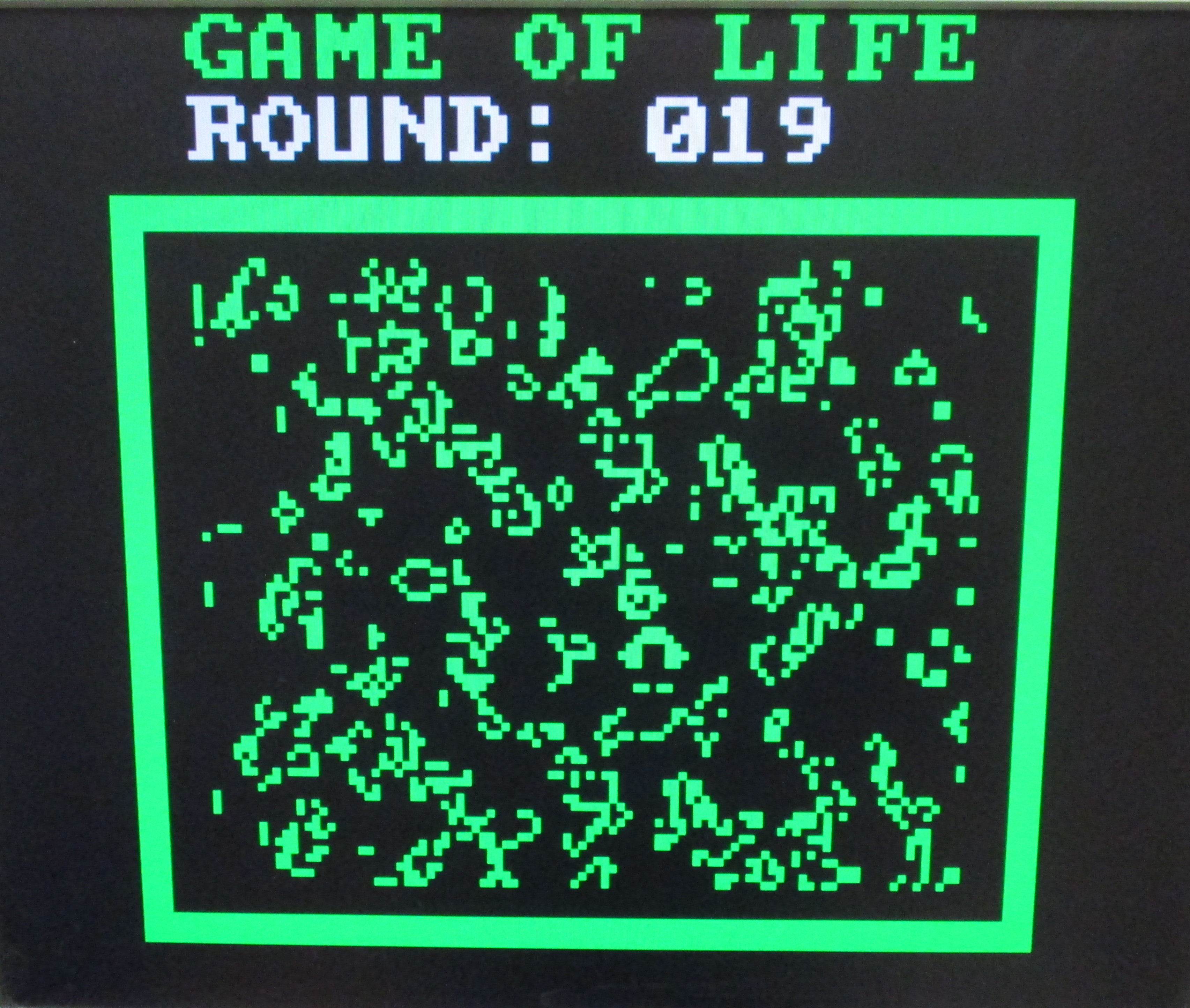
Started testing the new VGA controller with space invaders, but rather than finishing this game (tooo much work :), i decided to go classic with Conway's Game of Life. This is a cellular automaton created by John Conway in 1970, simulating artificial life. This game's world is a two-dimensional grid, each grid cell is either alive or dead. The interactions between cells determine if they survive or die:
This world's grid is initialised to a random state, each cell being set to a live or dead state. This present state is then used to calculate each cells next state i.e. these calculations are performed in parallel. Each cell is then updated simultaneously to its next state, this being called a "tick", or a round. The process is repeated, generating future generations, life expanding as cells reproduce, or shrink as they die, as shown in figure 1. A video of this "game" in action is available here: (Link).
Note, another reason for not finishing off the space invaders games was that i was looking for a simpler case study that would illustrate the complexities of implementing different data types on this processor e.g. bit arrays. A case study that looked at the overheads in processing these non-standard data types i.e. data that is not unsigned or signed numbers, and the "complexities" of working on a system with limited memory resources. Then using this base system explore how the processing performance of the system could be improved by adding new instructions i.e. to improve simulation speed, or allow bigger worlds to be simulated.
Figure 1 : Games of life
The maximum world size for this game is limited to the size of the screen i.e. what can be displayed, with each pixel representing one cell. For the video controller used in this system this is 160 x 120 pixels, therefore:
Number of cells = 160 x 120 = 19,200
To implement the rules that are used to calculate the state of each cell the software needs to represents each cells present and next states i.e. alive or dead. If each cell's state is stored in one memory location this would require:
Memory locations = 160 x 120 x 2 = 38,400
This is almost ten times the amount of memory the simpleCPU_v1d system has i.e. 4096 x 16bit. However, as each cell only has two states i.e. alive=1 or dead=0, the number of memory locations needed can be reduce by a factor of 16 (memory width). To represent the present state (1bit) and the next state (1bit) of each cell requires:
Memory locations = (160 x 120 x 2) / 16 = 2400 words
However, even with this reduction, this data-set still puts a significant strain on the simpleCPU's memory resources i.e. we need some memory for game code and other variables. Therefore, in the final game the world size will probably need to be reduced.
To calculate the state of each cell the state of its neighbouring cells needs to be examined, as shown in figure 2. If the cell state being calculated is X0Y0 then the state of its neighbouring eight cell needs to be examined and the previous rules applied.
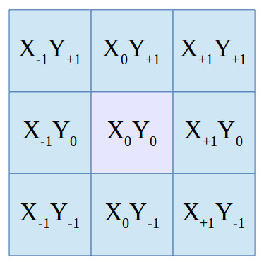
Figure 2 : cell calculation grid
An obvious edge case for these calculations are the edges of this 2D world. To calculate the state of the top left cell (0,0), we would need to see outside of this world. Alternatively, we could connect the opposite edges i.e. left to right, top to bottom, and form a toroidal world, as shown in figure 3. However, to keep things simple, for this implementation i'm going to make this outer ring static i.e. once initialised to their initial value the state of these cells are not updated, these cells can not change, they are immortal and can not die :).
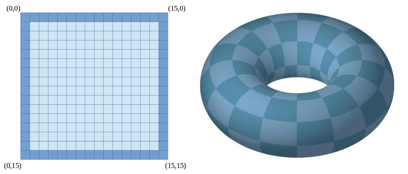
Figure 3 : world edges (left), toroidal world (right)
To support the creation and calculations used to process these cells i created a set of macros:
CREATE_BIT_ARRAY
create_bit_array( SIZE ) : reserves and initialises to zero SIZE/16 memory locations.
GET_BIT_ARRAY
get_bit_array( BASE, INDEX ) : macro passed the base address of the first memory location used to implement the bit_array and the bit index into that array to be accessed. Macro returns cell state 0=dead, 1=alive.
get_bit_array( BASE ) : macro passed the base address of the first memory location used to implement the bit_array, the bit index into that array is passed via the variable bit_array_index. Macro returns cell state 0=dead, 1=alive.
SET_BIT_ARRAY
set_bit_array( BASE, INDEX ) : macro passed the base address of the first memory location used to implement the bit_array and the bit index into that array. State of this bit set to 1=alive.
set_bit_array( BASE ) : macro passed the base address of the first memory location used to implement the bit_array, the bit index into that array is passed via the variable bit_array_index. State of this bit set to 1=alive.
CLR_BIT_ARRAY
clr_bit_array( BASE, INDEX ) : macro passed the base address of the first memory location used to implement the bit_array and the bit index into that array. State of this bit set to 0=dead.
clr_bit_array( BASE ) : macro passed the base address of the first memory location used to implement the bit_array, the bit index into that array is passed via the variable bit_array_index. State of this bit set to 0=dead.
These macros and the house keeping macros they use (movea, moved and rotate_left) are shown below:
# move 12bit address into register - movea( ADDR )
# ------------------------------------------------

define( movea, ``move $1 eval( ( $2 & 0xF00 ) >> 4)'
  and $1 0xFF
  asl $1
  asl $1
  asl $1
  asl $1
  `or $1 eval( $2 & 0xFF )'')

# move 16 bit data into register - moved( DATA )
# ----------------------------------------------

define( moved, `move $1 eval( ($2 & 0xFF00) >> 8)
  asl $1
  asl $1
  asl $1
  asl $1
  asl $1
  asl $1
  asl $1
  asl $1
  or $1 eval( $2 & 0xFF )')

# rotate left - rotate_left( BITS )
# ---------------------------------

define( rotate_left, `
ifelse(eval($2==15), 1, `
  rol $1
  rol $1
  rol $1
  rol $1
  rol $1
  rol $1
  rol $1
  rol $1
  rol $1
  rol $1
  rol $1
  rol $1
  rol $1
  rol $1
  rol $1',)

  ... more IFs for 14 to 5 ...

ifelse(eval($2==4), 1, `
  rol $1
  rol $1
  rol $1
  rol $1',)
ifelse(eval($2==3), 1, `
  rol $1
  rol $1
  rol $1',)
ifelse(eval($2==2), 1, `
  rol $1
  rol $1',)
ifelse(eval($2==1), 1, `
  rol $1',)
')

# reserve space - space( SIZE )
# -----------------------------

define( space, `
    .data 0'dnl
`ifelse( eval( $1 - 1 ), 0, `
    .data 0', `space( eval( $1 - 1 ) )')' )

# create array - create_bit_array( SIZE )
# ---------------------------------------

define( create_bit_array, `space(eval( $1 / 16 ))' )

# get_array_bit( BASE, INDEX )
#                1     2
# get_array_bit( BASE )
#                1

define( get_array_bit, `
ifelse(eval($#==1), 1, `
  movea( RC, $1 )
  load RA bit_array_index
  move RB RA
  rotate_left( RA, 12 )
  add RC RA
  load RA (RC)
  and RB 0x0F
  call get_array_bit_subroutine',)

ifelse(eval($#==2), 1, `
  movea( RC, $1 )
  moved( RD, $2 )
  move RB RD
  rotate_left( RD, 12 )
  add RC RD
  load RA (RC)
  and RB 0x0F
  call get_array_bit_subroutine',)
')

# set_array_bit( BASE, INDEX )
#                1     2
# set_array_bit( BASE )
#                1

define( set_array_bit, `
ifelse(eval($#==1), 1, `
  movea( RC, $1 )
  load RA bit_array_index
  move RB RA
  rotate_left( RA, 12 )
  add RC RA
  load RA (RC)
  and RB 0x0F
  call set_array_bit_subroutine',)

ifelse(eval($#==2), 1, `
  movea( RC, $1 )
  moved( RD, $2 )
  move RB RD
  rotate_left( RD, 12 )
  add RC RD
  load RA (RC)
  and RB 0x0F
  call set_array_bit_subroutine',)
')

# clr_array_bit( BASE, INDEX )
#                1     2
# clr_array_bit( BASE )
#                1

define( clr_array_bit, `
ifelse(eval($#==1), 1, `
  movea( RC, $1 )
  load RA bit_array_index
  move RB RA
  rotate_left( RA, 12 )
  add RC RA
  load RA (RC)
  and RB 0x0F
  call clr_array_bit_subroutine',)

ifelse(eval($#==2), 1, `
  movea( RC, $1 )
  moved( RD, $2 )
  move RB RD
  rotate_left( RD, 12 )
  add RC RD
  load RA (RC)
  and RB 0x0F
  call clr_array_bit_subroutine',)
')
The subroutines (and macros) used to implement these macros are available here (Link). The subroutine: set_array_bit_subroutine is shown below. This illustrates the processing overheads associated with this type of bit manipulation i.e. a lot of bit shuffling, each bit update needs 16 ROL instructions. This inefficiency is due to the limited instruction-set supported by the simpleCPU_v1d and that the rotate left instruction (ROL) can only move the bits in a register one bit position. A second issue is that the current instruction-set can not implement SWITCH/CASE statements, therefore, it has to use basic IF-THEN-ELSE structures i.e. processing/selection time is data dependent, 0 index = fast, 15 index = slow.
# ------------------
# - SET ARRAY BIT -
# ------------------

# RA - data
# RB - index
# RC - address

set_array_bit_subroutine:
    add RB 0x00
    jumpz set_array_bit_0
    sub RB 1
    jumpz set_array_bit_1
    sub RB 1
    jumpz set_array_bit_2
    sub RB 1
    jumpz set_array_bit_3
    sub RB 1
    jumpz set_array_bit_4
    sub RB 1
    jumpz set_array_bit_5
    sub RB 1
    jumpz set_array_bit_6
    sub RB 1
    jumpz set_array_bit_7
    sub RB 1
    jumpz set_array_bit_8
    sub RB 1
    jumpz set_array_bit_9
    sub RB 1
    jumpz set_array_bit_A
    sub RB 1
    jumpz set_array_bit_B
    sub RB 1
    jumpz set_array_bit_C
    sub RB 1
    jumpz set_array_bit_D
    sub RB 1
    jumpz set_array_bit_E

set_array_bit_F:
    rotate_left( RA, 1 )
    or RA 0x01
    rotate_left( RA, 15 )
    store RA (RC)
    ret
set_array_bit_0:
    or RA 0x01
    store RA (RC)
    ret
set_array_bit_1:
    rotate_left( RA, 15 )
    or RA 0x01
    rotate_left( RA, 1 )
    store RA (RC)
    ret
set_array_bit_2:
    rotate_left( RA, 14 )
    or RA 0x01
    rotate_left( RA, 2 )
    store RA (RC)
    ret
set_array_bit_3:
    rotate_left( RA, 13 )
    or RA 0x01
    rotate_left( RA, 3 )
    store RA (RC)
    ret
set_array_bit_4:
    rotate_left( RA, 12 )
    or RA 0x01
    rotate_left( RA, 4 )
    store RA (RC)
    ret
set_array_bit_5:
    rotate_left( RA, 11 )
    or RA 0x01
    rotate_left( RA, 5 )
    store RA (RC)
    ret
set_array_bit_6:
    rotate_left( RA, 10 )
    or RA 0x01
    rotate_left( RA, 6 )
    store RA (RC)
    ret
set_array_bit_7:
    rotate_left( RA, 9 )
    or RA 0x01
    rotate_left( RA, 7 )
    store RA (RC)
    ret
set_array_bit_8:
    rotate_left( RA, 8 )
    or RA 0x01
    rotate_left( RA, 8 )
    store RA (RC)
    ret
set_array_bit_9:
    rotate_left( RA, 7 )
    or RA 0x01
    rotate_left( RA, 9 )
    store RA (RC)
    ret
set_array_bit_A:
    rotate_left( RA, 6 )
    or RA 0x01
    rotate_left( RA, 10 )
    store RA (RC)
    ret
set_array_bit_B:
    rotate_left( RA, 5 )
    or RA 0x01
    rotate_left( RA, 11 )
    store RA (RC)
    ret
set_array_bit_C:
    rotate_left( RA, 4 )
    or RA 0x01
    rotate_left( RA, 12 )
    store RA (RC)
    ret
set_array_bit_D:
    rotate_left( RA, 3 )
    or RA 0x01
    rotate_left( RA, 13 )
    store RA (RC)
    ret
set_array_bit_E:
    rotate_left( RA, 2 )
    or RA 0x01
    rotate_left( RA, 14 )
    store RA (RC)
    ret
To reduce code size and improve processing performance we can improve the simpleCPU_v1d's instruction-set, however, to ensure backwards compatibility there are limits i.e. we want old code to still function correctly on this new hardware. The default instruction set is shown below:
# INSTR   IR15 IR14 IR13 IR12 IR11 IR10 IR09 IR08 IR07 IR06 IR05 IR04 IR03 IR02 IR01 IR00

# MOVE    0    0    0    0    RD   RD   X    X    K    K    K    K    K    K    K    K
# ADD     0    0    0    1    RD   RD   X    X    K    K    K    K    K    K    K    K
# SUB     0    0    1    0    RD   RD   X    X    K    K    K    K    K    K    K    K
# AND     0    0    1    1    RD   RD   X    X    K    K    K    K    K    K    K    K

# LOAD    0    1    0    0    A    A    A    A    A    A    A    A    A    A    A    A
# STORE   0    1    0    1    A    A    A    A    A    A    A    A    A    A    A    A
# ADDM    0    1    1    0    A    A    A    A    A    A    A    A    A    A    A    A
# SUBM    0    1    1    1    A    A    A    A    A    A    A    A    A    A    A    A

# JUMPU   1    0    0    0    A    A    A    A    A    A    A    A    A    A    A    A
# JUMPZ   1    0    0    1    A    A    A    A    A    A    A    A    A    A    A    A
# JUMPNZ  1    0    1    0    A    A    A    A    A    A    A    A    A    A    A    A
# JUMPC   1    0    1    1    A    A    A    A    A    A    A    A    A    A    A    A

# CALL    1    1    0    0    A    A    A    A    A    A    A    A    A    A    A    A

# OR      1    1    0    1    RD   RD   X    X    K    K    K    K    K    K    K    K
# XOP1    1    1    1    0    U    U    U    U    U    U    U    U    U    U    U    U  -- NOT IMPLEMENTED

# RET     1    1    1    1    X    X    X    X    X    X    X    X    0    0    0    0
# MOVE    1    1    1    1    RD   RD   RS   RS   X    X    X    X    0    0    0    1
# LOAD    1    1    1    1    RD   RD   RS   RS   X    X    X    X    0    0    1    0  -- REG INDIRECT
# STORE   1    1    1    1    RD   RD   RS   RS   X    X    X    X    0    0    1    1  -- REG INDIRECT
# ROL     1    1    1    1    RSD  RSD  X    X    X    X    X    X    0    1    0    0

# ROR     1    1    1    1    RSD  RSD  X    X    X    X    X    X    0    1    0    1  -- NOT IMPLEMENTED
# ADD     1    1    1    1    RD   RD   RS   RS   X    X    X    X    0    1    1    0  -- NOT IMPLEMENTED
# SUB     1    1    1    1    RD   RD   RS   RS   X    X    X    X    0    1    1    1  -- NOT IMPLEMENTED
# AND     1    1    1    1    RD   RD   RS   RS   X    X    X    X    1    0    0    0  -- NOT IMPLEMENTED
# OR      1    1    1    1    RD   RD   RS   RS   X    X    X    X    1    0    0    1  -- NOT IMPLEMENTED
# XOR     1    1    1    1    RD   RD   RS   RS   X    X    X    X    1    0    1    0
# ASL     1    1    1    1    RD   RD   RS   RS   X    X    X    X    1    0    1    1

# XOP2    1    1    1    1    RD   RD   RS   RS   X    X    X    X    1    1    0    0  -- NOT IMPLEMENTED
# XOP3    1    1    1    1    RD   RD   RS   RS   X    X    X    X    1    1    0    1  -- NOT IMPLEMENTED
# XOP4    1    1    1    1    RD   RD   RS   RS   X    X    X    X    1    1    1    0  -- NOT IMPLEMENTED
# XOP5    1    1    1    1    RD   RD   RS   RS   X    X    X    X    1    1    1    1  -- NOT IMPLEMENTED

0 = Logic 0, 1 = Logic 1, U = Undefined, X = Unused, A = Address, K = Constant (Immediate).

RD = Destination register, RS = Source register.

Functionality of XOP1, XOP2, XOP3, XOP4 and XOP5 are not defined.
The current 1-operand rotate left instruction (ROL) is shown in figure 4 (top). As we can see there are five "not used" bits available that can be used to specify the rotate/shift value (amount) i.e. 0 - 15 bit positions. Note, a rotate of 16 is the same as a rotate of 0. Therefore, we can use four of these bits to specify the shift value, allowing a single instruction to rotate the bits within a register from 0 to 15 bit positions. This however raises a backwards comparability issue. The machine code for the old ROL instruction will have a "shift" value of zero, BUT, as it does not use this bit field it will rotate the bits within the register one bit position. However, the new ROL would not i.e. it would perform a shift of 0 bit positions. To get round this issue the shift value for the new ROL instruction will be limited to 1 - 15 bit positions, with a 0 value being treated as a shift of 1. Note, this is due to the shift operand being an immediate value i.e. static. Therefore, there is no practical reason for a programmer to specify a 0 shift, as this instruction would not do anything. Also supporting a 0 shift would increase hardware complexity.
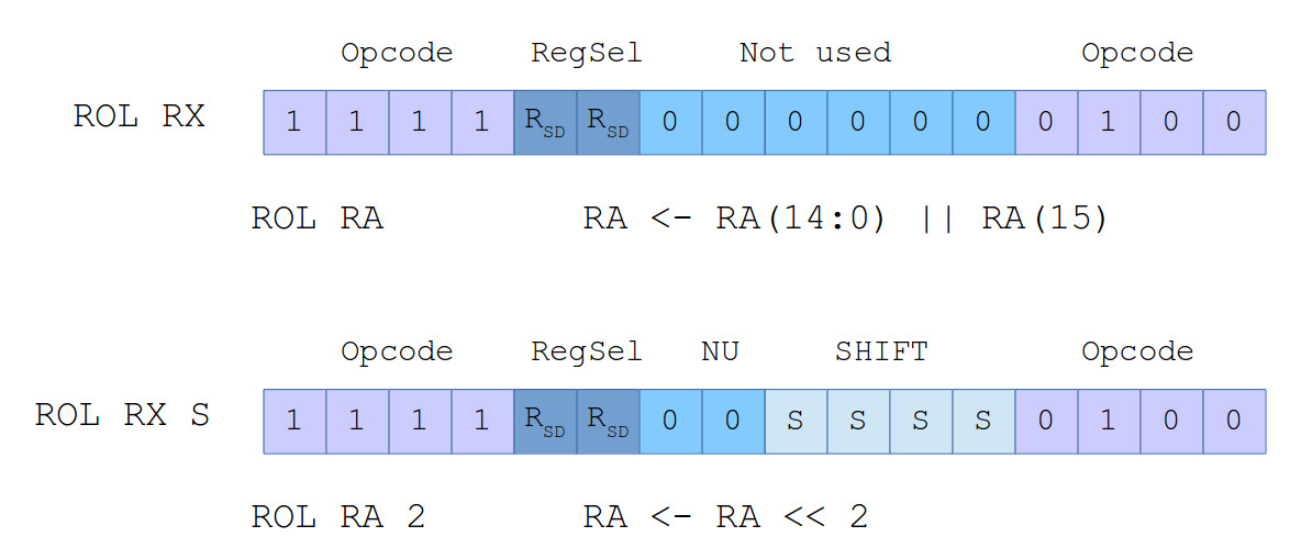
Figure 4 : old ROL (top), new ROL (bottom) instructions
In hardware a variable length rotate/shift is typically implemented using a barrel shifter (Link). Before implementing this new hardware, i had a read around to find the best ways of implementing this functionality on an FGPA. There are a number of different approaches focusing on minimising the amount of hardware needed i.e. reduce the size and number of multiplexers used. However, that looked complicated so i decided to keep things simple and went for a VHDL implementation i.e. to be lazy and handing over the optimisation task to the synthesise tools :). The barrel shifters VHDL is shown below. Note, these component implement the rotate\shift left function, the rotate\shift right components are comparable, just the opposite direction.
-- =============================================================================================================
-- *
-- * Copyright (c) Mike
-- *
-- * File Name: rotate_left_logic.vhd
-- *
-- * Version: V1.0
-- *
-- * Release Date:
-- *
-- * Author(s): M.Freeman
-- *
-- * Description: simple 16bit barrel shifter
-- *
-- * Conditions of Use: THIS CODE IS COPYRIGHT AND IS SUPPLIED "AS IS" WITHOUT WARRANTY OF ANY KIND, INCLUDING,
-- *                    BUT NOT LIMITED TO, ANY IMPLIED WARRANTY OF MERCHANTABILITY AND FITNESS FOR A
-- *                    PARTICULAR PURPOSE.
-- *
-- * Notes:
-- *
-- =============================================================================================================

library IEEE;
use IEEE.STD_LOGIC_1164.ALL;
use IEEE.std_logic_unsigned.all;

entity rotate_left_logic is
Port (
  A    : in  STD_LOGIC_VECTOR (15 downto 0);
  Y    : out STD_LOGIC_VECTOR (15 downto 0);
  COUT : out STD_LOGIC;
  SEL  : in  STD_LOGIC_VECTOR (3 downto 0));
end rotate_left_logic;

architecture rotate_left_logic_arch of rotate_left_logic is
begin

  mux_logic: PROCESS( A, SEL )
  BEGIN
    CASE SEL is
      WHEN "0001"  =>
        Y    <= A(14 DOWNTO 0) & A(15);             -- EDCBA9876543210F
        COUT <= A(15);
      WHEN "0010"  =>
        Y    <= A(13 DOWNTO 0) & A(15 DOWNTO 14);   -- DCBA9876543210FE
        COUT <= A(14);
      WHEN "0011"  =>
        Y    <= A(12 DOWNTO 0) & A(15 DOWNTO 13);   -- CBA9876543210FED
        COUT <= A(13);
      WHEN "0100"  =>
        Y    <= A(11 DOWNTO 0) & A(15 DOWNTO 12);   -- BA9876543210FEDC
        COUT <= A(12);
      WHEN "0101"  =>
        Y    <= A(10 DOWNTO 0) & A(15 DOWNTO 11);   -- A9876543210FEDCB
        COUT <= A(11);
      WHEN "0110"  =>
        Y    <= A(9 DOWNTO 0)  & A(15 DOWNTO 10);   -- 9876543210FEDCBA
        COUT <= A(10);
      WHEN "0111"  =>
        Y    <= A(8 DOWNTO 0)  & A(15 DOWNTO 9);    -- 876543210FEDCBA9
        COUT <= A(9);
      WHEN "1000"  =>
        Y    <= A(7 DOWNTO 0)  & A(15 DOWNTO 8);    -- 76543210FEDCBA98
        COUT <= A(8);
      WHEN "1001"  =>
        Y    <= A(6 DOWNTO 0)  & A(15 DOWNTO 7);    -- 6543210FEDCBA987
        COUT <= A(7);
      WHEN "1010"  =>
        Y    <= A(5 DOWNTO 0)  & A(15 DOWNTO 6);    -- 543210FEDCBA9876
        COUT <= A(6);
      WHEN "1011"  =>
        Y    <= A(4 DOWNTO 0)  & A(15 DOWNTO 5);    -- 43210FEDCBA98765
        COUT <= A(5);
      WHEN "1100"  =>
        Y    <= A(3 DOWNTO 0)  & A(15 DOWNTO 4);    -- 3210FEDCBA987654
        COUT <= A(4);
      WHEN "1101"  =>
        Y    <= A(2 DOWNTO 0)  & A(15 DOWNTO 3);    -- 210FEDCBA9876543
        COUT <= A(3);
      WHEN "1110"  =>
        Y    <= A(1 DOWNTO 0)  & A(15 DOWNTO 2);    -- 10FEDCBA98765432
        COUT <= A(2);
      WHEN "1111"  =>
        Y    <= A(0)           & A(15 DOWNTO 1);    -- 0FEDCBA987654321
        COUT <= A(1);
      WHEN OTHERS  =>
        Y    <= A(14 DOWNTO 0) & A(15);             -- EDCBA9876543210F
        COUT <= A(15);
    END CASE;
  END PROCESS;

end rotate_left_logic_arch;
-- =============================================================================================================
-- *
-- * Copyright (c) Mike
-- *
-- * File Name: shift_left_mask.vhd
-- *
-- * Version: V1.0
-- *
-- * Release Date:
-- *
-- * Author(s): M.Freeman
-- *
-- * Description: simple bitwise shift left/right mask
-- *
-- * Conditions of Use: THIS CODE IS COPYRIGHT AND IS SUPPLIED "AS IS" WITHOUT WARRANTY OF ANY KIND, INCLUDING,
-- *                    BUT NOT LIMITED TO, ANY IMPLIED WARRANTY OF MERCHANTABILITY AND FITNESS FOR A
-- *                    PARTICULAR PURPOSE.
-- *
-- * Notes:
-- *
-- =============================================================================================================

library IEEE;
use IEEE.STD_LOGIC_1164.ALL;

entity shift_left_mask is
Port (
  A    : in  STD_LOGIC_VECTOR (15 downto 0);
  Y    : out STD_LOGIC_VECTOR (15 downto 0);
  SEL  : in  STD_LOGIC_VECTOR (3 downto 0));
end shift_left_mask;

architecture shift_left_mask_arch of shift_left_mask is
  signal MASK : STD_LOGIC_VECTOR(15 DOWNTO 0);
begin

  Y <= A and MASK;

  mask_logic: PROCESS( A )
  BEGIN
    CASE SEL is
      WHEN "0001"  => MASK <= "1111111111111110";
      WHEN "0010"  => MASK <= "1111111111111100";
      WHEN "0011"  => MASK <= "1111111111111000";
      WHEN "0100"  => MASK <= "1111111111110000";
      WHEN "0101"  => MASK <= "1111111111100000";
      WHEN "0110"  => MASK <= "1111111111000000";
      WHEN "0111"  => MASK <= "1111111110000000";
      WHEN "1000"  => MASK <= "1111111100000000";
      WHEN "1001"  => MASK <= "1111111000000000";
      WHEN "1010"  => MASK <= "1111110000000000";
      WHEN "1011"  => MASK <= "1111100000000000";
      WHEN "1100"  => MASK <= "1111000000000000";
      WHEN "1101"  => MASK <= "1110000000000000";
      WHEN "1110"  => MASK <= "1100000000000000";
      WHEN "1111"  => MASK <= "1000000000000000";
      WHEN OTHERS  => MASK <= "1111111111111110";
    END CASE;
  END PROCESS;
end shift_left_mask_arch;
Passing this through the synthesis tools produces the hardware shown in figure 5. Looking at the auto-generated technology schematic it looks like this VHDL produces a MUX tree, made up of 64 two-input bit-multiplexers, with a propagation delay of approximately 14.844ns (on an old spartan3E FPGA), which isn't so bad. The complete rotate/shift component is shown in figure 6, a little non-optimal, shift\rotates divided into left\right components, implemented using the same "rotate" barrel shifter. To convert the rotated result into an arithmetic shift this output is then ANDed with an appropriate mask. Included in figure 6 is the and_or_xor component, used to implement the bitwise functions.
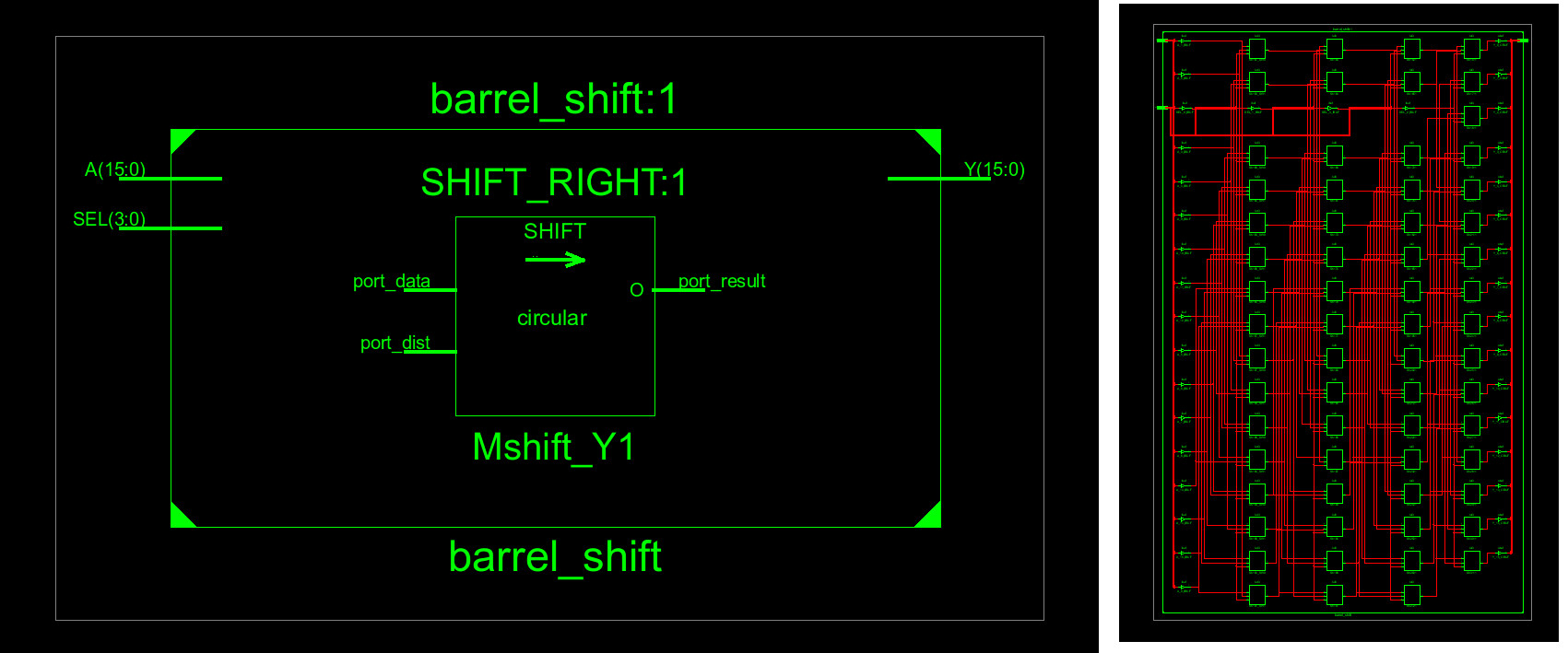
Figure 5 : barrel shifter on the FPGA
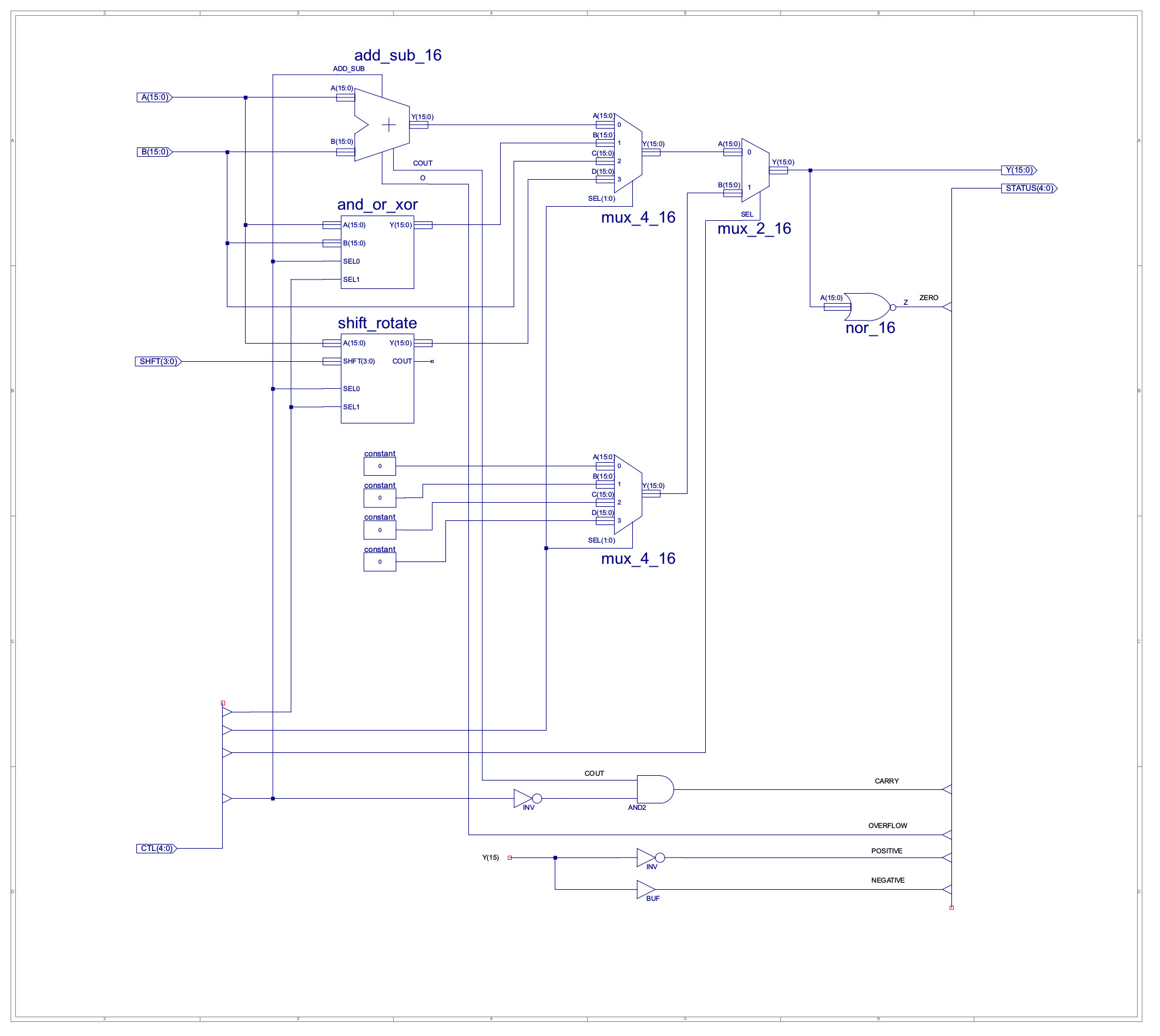
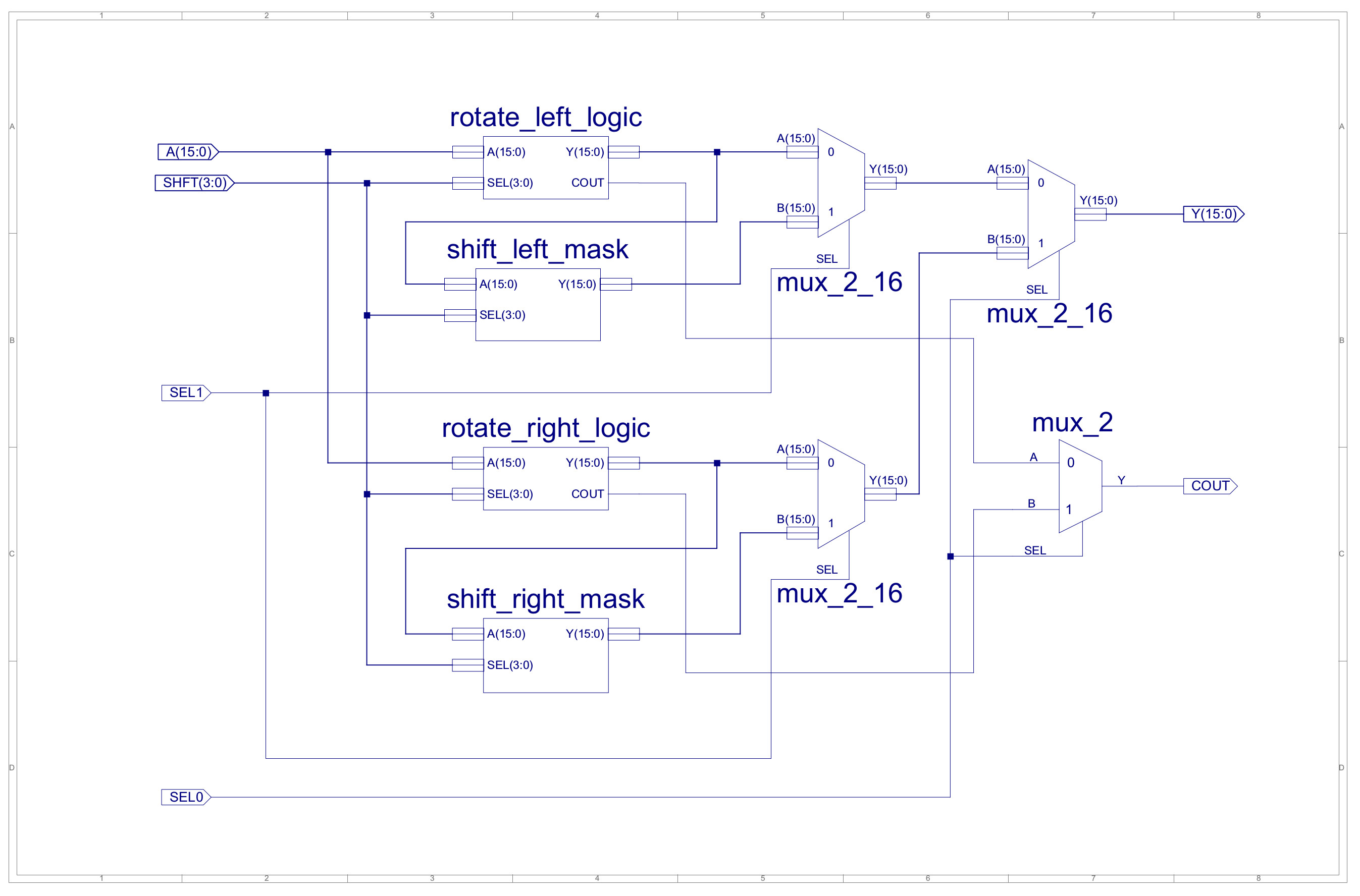
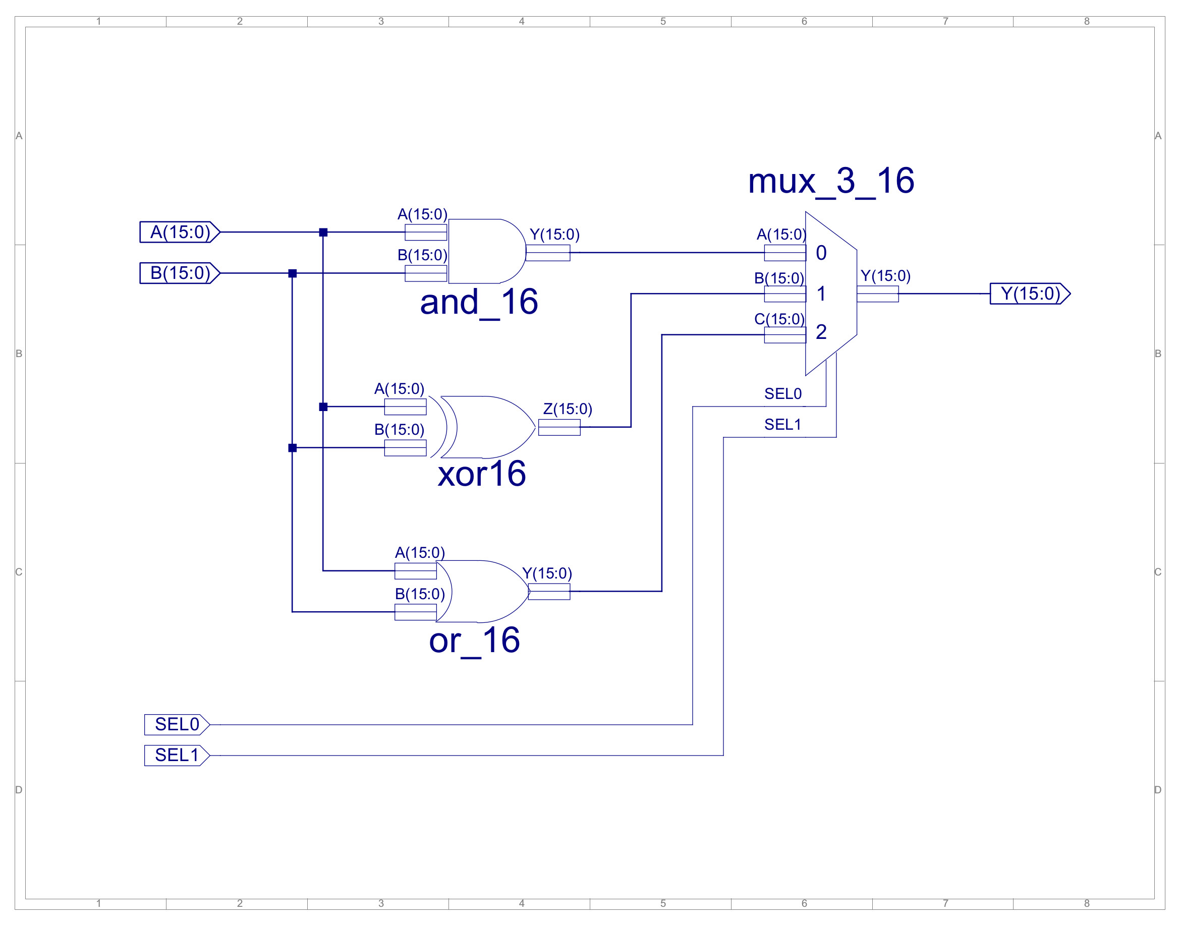
Figure 6 : new ALU (top), shift_rotate (middle), and_or_xor (bottom) component.
To help speed up the selection process used in the subroutines that process the bit_array i.e. the code used to select the bit to be accessed/modified, we need a SWITCH/CASE statement. The classic method of implementing a SWITCH/CASE statement in assembler is to use a jump table i.e. a register-indirect JUMP instruction. Therefore, we need another new instruction. This raises the question of how should each instruction be encoded i.e. what is the most efficient implementation, how can we maximise the number of instructions, given the backwards compatibility limitations? When designing the SimpleCPU the initial allocation of opcodes were made with a teaching focus i.e. to help discuss/highlight different addressing modes e.g. the top two bits of the top opcode identifies the addressing mode used 00 = Immediate, 01 = Absolute, 10 = Direct, 11 = Register. However, this allocation did not consider the final instruction-set, the focus was to show how the instruction-set of the simpleCPU_v1a could be expanded upon when we moved to the simpleCPU_v1d. Therefore, after some thought, going to stick with the basic structure, keeping the link to the simpleCPU_v1a, but going to break the backwards compatibility restrictions a little. The instructions i'm going to "break" have not been implemented yet, so i'm not actually breaking anything at the moment, just redefining. Therefore, the new, improved and updated instruction-set is:
# INSTR   IR15 IR14 IR13 IR12 IR11 IR10 IR09 IR08 IR07 IR06 IR05 IR04 IR03 IR02 IR01 IR00

# MOVE    0    0    0    0    RD   RD   X    X    K    K    K    K    K    K    K    K
# ADD     0    0    0    1    RD   RD   X    X    K    K    K    K    K    K    K    K
# SUB     0    0    1    0    RD   RD   X    X    K    K    K    K    K    K    K    K
# AND     0    0    1    1    RD   RD   X    X    K    K    K    K    K    K    K    K

# LOAD    0    1    0    0    A    A    A    A    A    A    A    A    A    A    A    A
# STORE   0    1    0    1    A    A    A    A    A    A    A    A    A    A    A    A
# ADDM    0    1    1    0    A    A    A    A    A    A    A    A    A    A    A    A
# SUBM    0    1    1    1    A    A    A    A    A    A    A    A    A    A    A    A

# JUMPU   1    0    0    0    A    A    A    A    A    A    A    A    A    A    A    A
# JUMPZ   1    0    0    1    A    A    A    A    A    A    A    A    A    A    A    A
# JUMPNZ  1    0    1    0    A    A    A    A    A    A    A    A    A    A    A    A
# JUMPC   1    0    1    1    A    A    A    A    A    A    A    A    A    A    A    A

# CALL    1    1    0    0    A    A    A    A    A    A    A    A    A    A    A    A

# OR      1    1    0    1    RD   RD   X    X    K    K    K    K    K    K    K    K
# XOP1    1    1    1    0    U    U    U    U    U    U    U    U    U    U    U    U  -- NOT IMPLEMENTED

# RET     1    1    1    1    X    X    X    X    X    X    X    X    0    0    0    0

# MOVE    1    1    1    1    RD   RD   RS   RS   X    X    X    X    0    0    0    1
# LOAD    1    1    1    1    RD   RD   RS   RS   X    X    X    X    0    0    1    0  -- REG INDIRECT
# STORE   1    1    1    1    RD   RD   RS   RS   X    X    X    X    0    0    1    1  -- REG INDIRECT
# ROL     1    1    1    1    RSD  RSD  X    0    S    S    S    S    0    1    0    0
# ROR     1    1    1    1    RSD  RSD  X    1    S    S    S    S    0    1    0    0

# ASL     1    1    1    1    RSD  RSD  X    0    S    S    S    S    0    1    0    1  -- NOT IMPLEMENTED
# ASR     1    1    1    1    RSD  RSD  X    1    S    S    S    S    0    1    0    1  -- NOT IMPLEMENTED

# ADD     1    1    1    1    RD   RD   RS   RS   X    X    X    X    0    1    1    0  -- NOT IMPLEMENTED
# SUB     1    1    1    1    RD   RD   RS   RS   X    X    X    X    0    1    1    1  -- NOT IMPLEMENTED
# AND     1    1    1    1    RD   RD   RS   RS   X    X    X    X    1    0    0    0  -- NOT IMPLEMENTED
# OR      1    1    1    1    RD   RD   RS   RS   X    X    X    X    1    0    0    1  -- NOT IMPLEMENTED
# XOR     1    1    1    1    RD   RD   RS   RS   X    X    X    X    1    0    1    0

# JUMP    1    1    1    1    RD   RD   X    X    X    X    X    X    1    0    1    1

# XOP2    1    1    1    1    RD   RD   RS   RS   X    X    X    X    1    1    0    0  -- NOT IMPLEMENTED
# XOP3    1    1    1    1    RD   RD   RS   RS   X    X    X    X    1    1    0    1  -- NOT IMPLEMENTED
# XOP4    1    1    1    1    RD   RD   RS   RS   X    X    X    X    1    1    1    0  -- NOT IMPLEMENTED
# XOP5    1    1    1    1    RD   RD   RS   RS   X    X    X    X    1    1    1    1  -- NOT IMPLEMENTED

0 = Logic 0, 1 = Logic 1, U = Undefined, X = Unused, A = Address, K = Constant (Immediate), S = Shift.

RD = Destination register, RS = Source register, RSD = Source / Destination register.

Functionality of XOP1, XOP2, XOP3, XOP4 and XOP5 are not defined.
The thought process here is that as the rotate (ROL & ROR) and shift (ASL & ASR) instructions will be using same "hardware", so i just need 1bit to switch between the rotate/shift left/right hardware i.e. instruction register bit IR08, allowing the same opcode to be used for both instructions. Note, could of used the same opcode for all four instructions i.e. used instruction bit IR09 to select between rotate/shift, but decided to keep them separate. This frees up the lower opcode 1011 for the register indirect jump. Note, also the focus here was to allow future expansion of the instruction-set to allow an external statck i.e. PUSH and POP instructions.
To test out this new hardware and the software changes to the assembler to support the new 2-operand rotate\shift instructions, i wrote the short test program below:
move ra 1     # init registers with test values
move rb 2
move rc 3
move rd 4

rol ra        # 0000 0000 0000 0001 = 0000 0000 0000 0010 = 0x0002
rol ra 1      # 0000 0000 0000 0010 = 0000 0000 0000 0100 = 0x0004
rol rb 3      # 0000 0000 0000 0010 = 0000 0000 0001 0000 = 0x0010
rol rc 7      # 0000 0000 0000 0011 = 0000 0001 1000 0000 = 0x0180
rol rd 15     # 0000 0000 0000 0100 = 0000 0000 0000 0010 = 0x0002

asl ra        # 0000 0000 0000 0100 = 0000 0000 0000 1000 = 0x0008
asl ra 1      # 0000 0000 0000 1000 = 0000 0000 0001 0000 = 0x0010
asl rb 3      # 0000 0000 0001 0000 = 0000 0000 1000 0000 = 0x0080
asl rc 7      # 0000 0001 1000 0000 = 1100 0000 0000 0000 = 0xC000
asl rd 15     # 0000 0000 0000 0010 = 0000 0000 0000 0001 = 0x0001

ror ra        # 0000 0000 0001 0000 = 0000 0000 0000 1000 = 0x0008
ror ra 1      # 0000 0000 0000 1000 = 0000 0000 0000 0100 = 0x0004
ror rb 3      # 0000 0000 0000 0010 = 0000 0000 0001 0000 = 0x0010
ror rc 7      # 0000 0000 0000 0011 = 0000 0001 1000 0000 = 0x0180
ror rd 15     # 0000 0000 0000 0100 = 0000 0000 0000 0010 = 0x0002

asr ra        # 0000 0000 0000 0100 = 0000 0000 0000 0010 = 0x0002
asr ra 1      # 0000 0000 0000 0010 = 0000 0000 0000 0001 = 0x0001
asr rb 3      # 0000 0000 0001 0000 = 0000 0000 0000 0010 = 0x0002
asr rc 7      # 0000 0001 1000 0000 = 0000 0000 0000 0011 = 0x0003
asr rd 15     # 0000 0000 0000 0010 = 0000 0000 0000 0000 = 0x0000
The waveform simulation trace for this program is shown in figure 7. If you examine the register value for RA,RB,RC and RD you can see they are the same as the test cases.
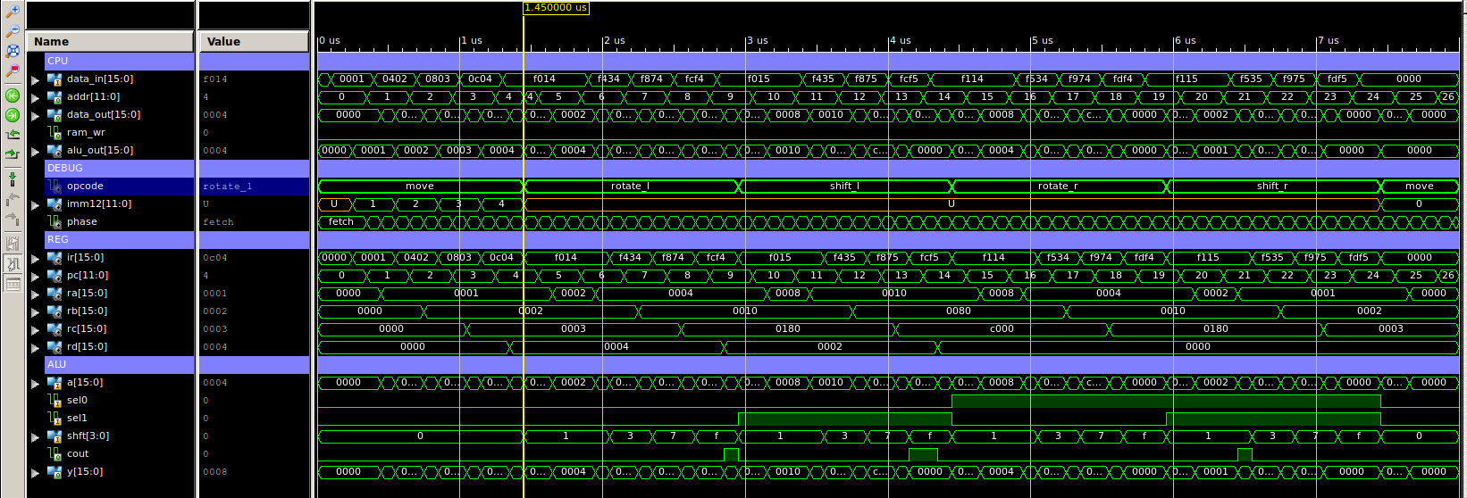
Figure 7 : simulation waveform
To implement the SWITCH/CASE software structure we can use the follow code. Note, RB stores the index 1 - 15, also rotate_left macros have been replaced with the new rol instructions.
set_array_bit_subroutine:
    movea( RA, set_array_bit_jump_table )
    add RA RB
    load RA (RB)
    jump (RA)

set_array_bit_jump_table:
    .data set_array_bit_0
    .data set_array_bit_1
    .data set_array_bit_2
    .data set_array_bit_3
    .data set_array_bit_4
    .data set_array_bit_5
    .data set_array_bit_6
    .data set_array_bit_7
    .data set_array_bit_8
    .data set_array_bit_9
    .data set_array_bit_A
    .data set_array_bit_B
    .data set_array_bit_C
    .data set_array_bit_D
    .data set_array_bit_E
    .data set_array_bit_F

set_array_bit_F:
    rol RA 1
    or RA 0x01
    rol RA 15
    store RA (RC)
    ret
set_array_bit_0:
    or RA 0x01
    store RA (RC)
    ret
set_array_bit_1:
    rol RA 15
    or RA 0x01
    rol RA 1
    store RA (RC)
    ret
set_array_bit_2:
    rol RA 14
    or RA 0x01
    rol RA 2
    store RA (RC)
    ret
set_array_bit_3:
    rol RA 13
    or RA 0x01
    rol RA 3
    store RA (RC)
    ret
set_array_bit_4:
    rol RA 12
    or RA 0x01
    rol RA 4
    store RA (RC)
    ret
set_array_bit_5:
    rol RA 11
    or RA 0x01
    rol RA 5
    store RA (RC)
    ret
set_array_bit_6:
    rol RA 10
    or RA 0x01
    rol RA 6
    store RA (RC)
    ret
set_array_bit_7:
    rol RA 9
    or RA 0x01
    rol RA 7
    store RA (RC)
    ret
set_array_bit_8:
    rol RA 8
    or RA 0x01
    rol RA 8
    store RA (RC)
    ret
set_array_bit_9:
    rol RA 7
    or RA 0x01
    rol RA 9
    store RA (RC)
    ret
set_array_bit_A:
    rol RA 6
    or RA 0x01
    rol RA 10
    store RA (RC)
    ret
set_array_bit_B:
    rol RA 5
    or RA 0x01
    rol RA 11
    store RA (RC)
    ret
set_array_bit_C:
    rol RA 4
    or RA 0x01
    rol RA 12
    store RA (RC)
    ret
set_array_bit_D:
    rol RA 3
    or RA 0x01
    rol RA 13
    store RA (RC)
    ret
set_array_bit_E:
    rol RA 2
    or RA 0x01
    rol RA 14
    store RA (RC)
    ret
A small BUT, is that to implement the register-indirect JUMP instruction needs a new MUX on the input to the PC i.e. JUMP instruction use the direct addressing mode, therefore, store the branch target address in the IR. With register-indirect addressing mode will need to get the address from the register file. For now just going to test out the basic software structures, so the first version of this game is going to use the original instruction-set, unmodified hardware. This will give a baseline processing performance which the new and improved system can then be compared to.
Implementing this games using the simple ROL instruction means we need a LOT of ROL instructions significantly increasing program size. As a result need to reduce the world size to 101 x 81 pixels, anything larger needed more than 4096 words i.e. i ran out of memory. To fill the empty screen decided to print a title and the tick\round number. These can be implemented using the same code developed for the space invaders game. Also thought it would be nice to draw a frame\border around the world. The VGA controller doesn't have a draw-line command at the moment, but it does support a draw-box command. Therefore, to draw the border, simply needed to draw a green box and then on top of this draw a smaller black box. A little inefficient, but easy to implement. As the border is only drawn once this is not a significant hit on processing performance. The only other functionality that needed to be implemented was the initial random state. Again, had a read around to see what was the best way to implement a random value in hardware. In the past i have always done this using a linear feedback shift register (LFSR), examples discussed here: (Link). However, got bit by the lazy bug again, so decided to go for a lookup table seeded by this python code:
import random

for i in range(256):
    data = random.randint(0,(2**16)-1)
    padded = str.format('0x{:04X}', data)
    outputString = ".data " + padded
    print outputString
This code produces an array of 256 random values, that can then be used to create further "random" values in the game e.g. adding, subtracting, incrementing, decrementing, shifting values from this table. The game runs for 1000 rounds i.e. tick count 0 to tick 999. When the max round count is reached the world is randomised again and the fun start over :). Screen shots and a video of this "game" in action is available here: (Link). Game code and macros for version 1 are available here: here (Macros)(Code).
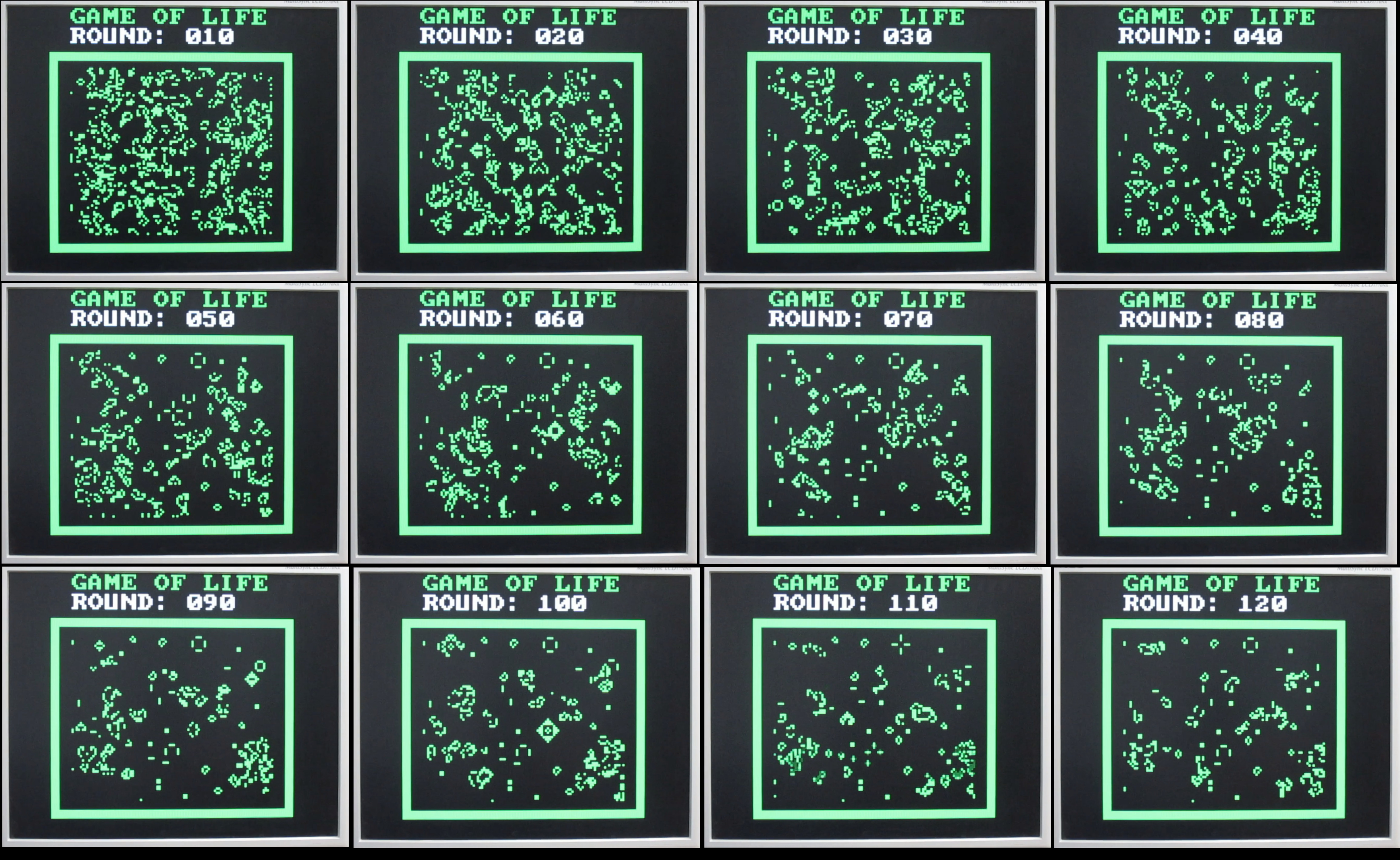
Figure 7 : Version 1 screenshots.
Need to Finish

This work is licensed under a Creative Commons Attribution-NonCommercial-NoDerivatives 4.0 International License.
Contact email: mike@simplecpudesign.com