
Figure 1 : pong
Objective 1 complete, we have implemented a real world processing task on the simpleCPU, processed an image (Link). Now its time for a more significant problem. The unspoken truth about computers is that they were invented so that we can play video games :). Its true, if you go back to 1950's and were to use EDSAC, one of the first stored program computers you could play noughts and crosses against the computer(Link). To keep things simple we are going to implement on the simpleCPU the first video game I ever played: Pong, as shown in figure 1. Pong is the original table tennis game in which two players hit a ball back and forth, if your opponent misses you score a point, first to 10 wins.
The ISE project files for this system can be downloaded here: (Link), basically the same structure, but with a few tweaks and a serial port. An updated python based assembler is also available here: (Link).
What display can we use?
To controller or not to controller?
The game
Cheap FPGA board
The first problem to overcome is: what kind of display can be attached to the FPGA board? Some of these FGPA boards do have HDMI interfaces, but these must be accessed through the onboard ARM core, rather than from the general purpose FPGA resources. Therefore, HDMI is impractical for this application. The next alternative considered was an VGA display (Link). This may sound complex, but the interface circuit is relatively simple to implement in an FPGA (Link), as shown in figure 2. Pins 1(R), 2(G) and 3(B) controls each pixel's colour, represented as an analogue voltage: 0v (no colour) to 1.0V (full colour). Pixel selection is controlled via the horizontal (pin 13) and vertical (pin 14) synchronisation control signals i.e. given a fixed scan rate these signals (pulses) define the start of a row and frame updates. The analogue voltages used to define the RGB value is generated by a simple resistor based digital to analogue converter (DAC) (Link) i.e. the 510, 1K, 2K and 4K resistors shown in figure 2. These are combined with a 75 ohm termination resistor within the monitor to form a potential divider circuit, as shown in figure 3. Therefore, by setting the associated digital outputs on the FPGA to a logic 0 (0V) or logic 1 (3.3V) we can generate the output voltages shown in figure 4.
Note, this analogue circuit was simulated using LTSpice (Link).
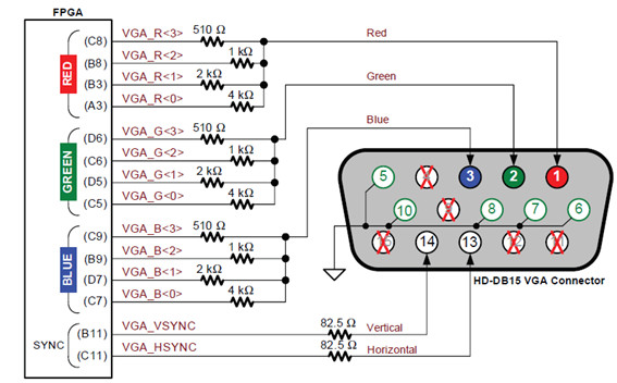
Figure 2 : VGA interface
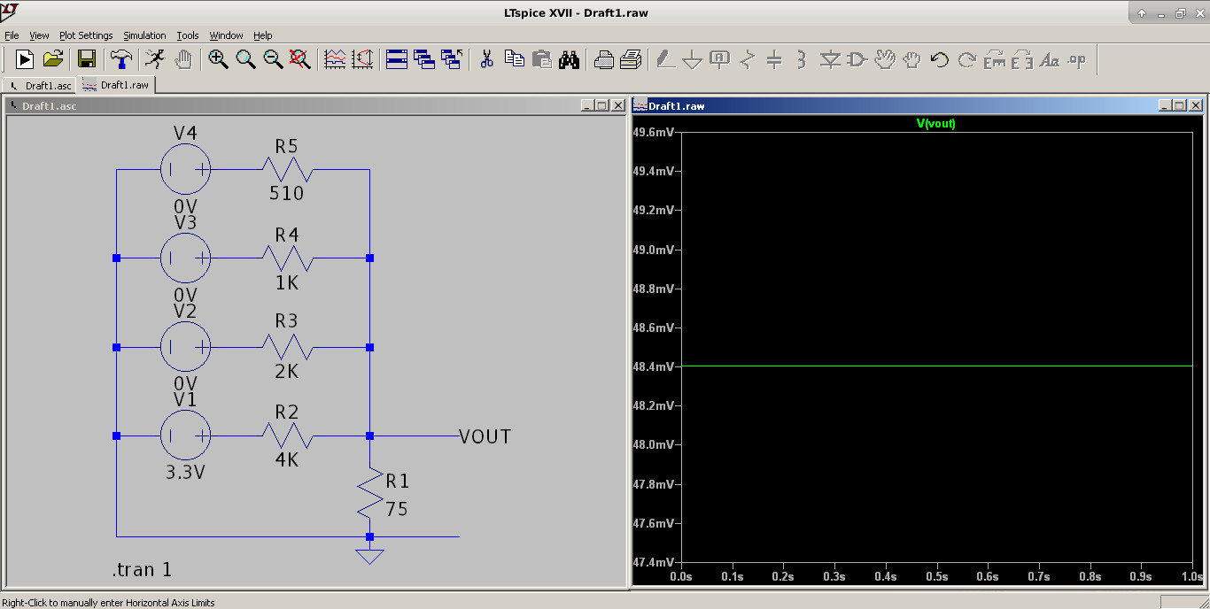
Figure 3 : DAC simulation
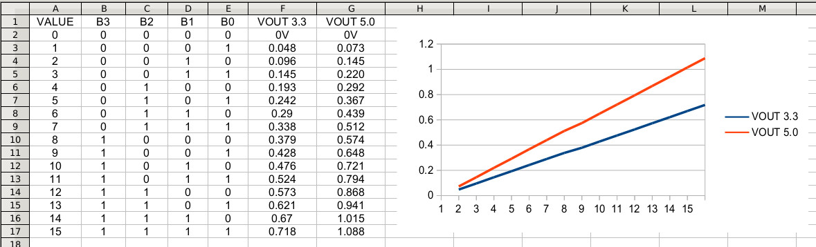
Figure 4 : DAC output voltage
I will probably build this display interface for a later model of the Pong game, but for lab usage it wasn't practical to have a second VGA monitor, as since the move to digital interfaces: display port, HDMI, DVI etc, analogue ones such as VGA are starting to become less common.
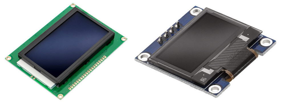
Figure 5 : LCD
The next display considered was a liquid crystal displays (LCD) panel, such as those shown in figure 5. These have either a parallel port or an I2C (Link) interface, which are again relatively simple to implement on the FPGA i.e. i have existing hardware / software for these from other projects. These displays could connect to the existing I2C interface or general purpose input/output ports (GPIO) on the FPGA board. Again, would be nice to implement this display for the "hand held" version of Pong, but decided against these from a cost view point i.e. everything starts to get expensive when you have to start kitting out a full lab :).
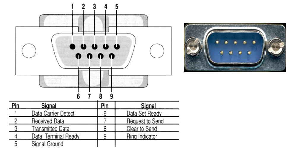
Figure 6 : RS232 connector
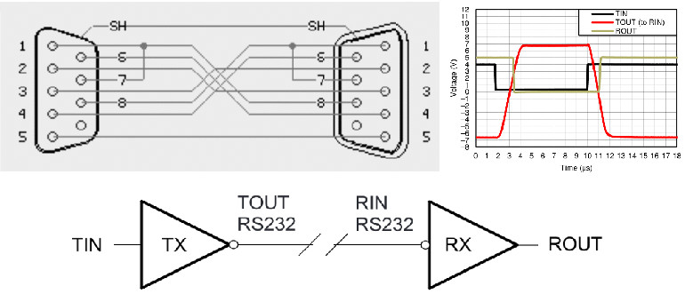
Figure 7 : RS232 wiring
This left plan B, the existing serial port shown in figure 6, and using the host PC's display. In previous versions of the simpleCPU we have used an RS232 (Link) serial port to print "Hello World" to a serial terminal running on the PC. However, in addition to sending alphanumeric characters we can also send command sequences to move the position of the cursor, print graphical symbols, or change the foreground / background colours. Typically these command sequences start with an ESC character (0x1B) followed by a "[" character (0x5B), allowing the terminal to identify that the characters that follow are a terminal command and should not be displayed. These command codes were adopted as an ANSI standard in 1981 and are therefore typical referred to as ANSI escape sequences, more information on these commands can be found here: (Link). To illustrate these commands consider the python code below:
Note, receiving a serial character across the RS232 interface, or printing a character to a terminal using a python program is basically the same thing so we can use this to our advantage when prototyping this system i.e. quicker to debug test out ideas using a high level language etc.
RED = chr(27)+"[41m"
BLACK = chr(27)+"[40m"
GOTO = chr(27)+"["

def main():
  print( RED + GOTO +"12;40H " +
               GOTO +"13;39H   " +
               GOTO +"14;40H " + BLACK )

if __name__=='__main__':
   main()
By constructing the correct ASCII text string we can now move the cursor to the desired position in the terminal windows i.e. in this example initially row 12, column 40. Then to change the background colour to RED and print spaces. These will form our low resolution "pixels", allowing use to drawing a red cross in the middle of the screen, as shown in figure 8.

Figure 8 : cross.py output
Now that we have the ability to set a "pixel's" colour and to move the cursor we can start to think about how we could implement the various graphical elements within the game. My first computer was a Commodore 64, so in tribute of this machine this game's graphics will be based on Sprites (Link). A Sprite is a simple way of organising your graphical elements within a display. Each element on screen is made from one or more sprites e.g. consider the score graphics shown in figure 9. These numbers are represented as an 3 x 5 array of pixels i.e. a sprite, that is stored in memory. An active (illuminated) pixels is represented by a logic 1, an inactive pixel as a logic 0. Therefore, the data array 7, 1, 7, 4, 7 represents the symbol "2".
Figure 9 : number sprites
In early computers the main software optimisation goal was to minimise memory usage, as typically these machines only had 16KB to 64KB of main memory. By reusing these graphical elements, plotting them at different positions you could give the illusion of movement, consider the iconic 11 x 8 space invader sprites shown in figure 10.


Figure 10 : space invader sprites
In the assembly program sprites are used to represent the score, bat, net and ball. To simplify coding these are stored at the end of the program using the sprite macro as shown below. In this example the values 2 and 3 are defined. The sprite macro converts this 3-bit data into a 3-bit integer i.e. each address will only hold three pixel values. This is not very efficient as the complete sprite could be stored in a single memory location. However, this approach was taken to simplify their representation within the program. Will refine in version 2 :)
# macro
define( sprite,`.data eval(($1 * 4) + ($2 * 2) + $3)' )

# number sprites
num_2:
    sprite( 1,1,1 )
    sprite( 0,0,1 )
    sprite( 1,1,1 )
    sprite( 1,0,0 )
    sprite( 1,1,1 )

num_3:
    sprite( 1,1,1 )
    sprite( 0,0,1 )
    sprite( 1,1,1 )
    sprite( 0,0,1 )
    sprite( 1,1,1 )
Note another advantage of using sprite base graphics is that you can reuse the same code to draw each graphical element, greatly simplifying code development / size.

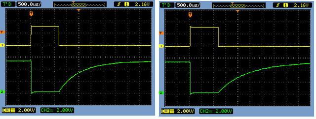
Figure 11 : variable resistor
The original Atari version of this game used two controllers based on rotational sensors, rotating anti-clockwise moves the bat up, clockwise down. These controllers used variable resistors to produce an analogue voltage to represent each bat's position. You can implement a simple analogue to digital convertors (ADC) (Link) using the resistor / capacitor circuit (Link), shown in figure 11. Converting these analogue signals into a digital representation the FPGA can use. In this circuit the FPGA board pulses the base of the transistor, discharging the capacitor. It then starts a timer on the FPGA (binary counter) and times how long it takes for the voltage on the capacitor to cross the logic 1 threshold. This delay being proportional the resistance of the variable resistor, as shown in figure 11. The plot on the left shows the delay for a small value of R and the plot on the right a larger value of R. From this delay we can therefore calculate the bat's position. This would be a workable solution, as we don't need a high resolution ADC (only 30-ish positions need to be represented), however, this would require some modifications to the FPGA boards in the lab, which would take some time to complete :(.
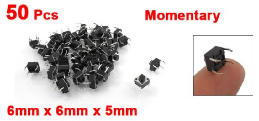
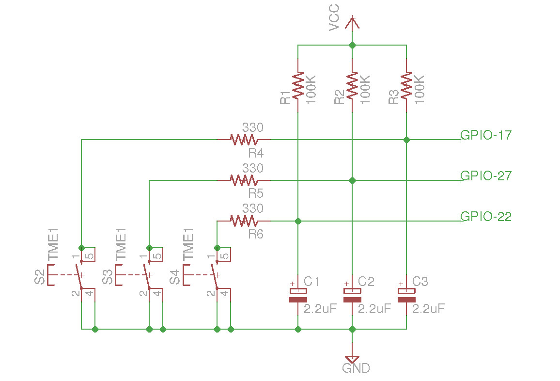
Figure 12 : push buttons
A simpler and cheap alternative is to use push buttons, as shown in figure 12 i.e. holding down the up or down button would move the bat in the desired direction at a constant speed. You would also need a button to trigger the ball's server function. One problem with these types of push buttons is that they suffer from contact bounce (Link) i.e. can generate false signals when pressed. To overcome this problem the RC debounce / filter circuit shown in figure 12 can be used. Again, did not take this approach for the lab owing to its labour costs, but i would use these for the hand held version of the game, as they offer a nice clean interface.
To simplify the simpleCPU implementation used in the lab i decided to use the PC's keyboard and send ASCII characters to the FPGA board via the terminal program. Also the the right hand player will be controlled using a simple AI, removing the need for two controllers, the left hand player keyboard controls are:
The final Pong system contains the simpleCPU_v1d, 4K x 16bit memory and a universal asynchronous receiver transmitter unit (UART). The UART (serial port) can operates in a full duplex mode i.e. receive and transmit serial data packets at the same time. This project can be downloaded from the link at the top of this page.
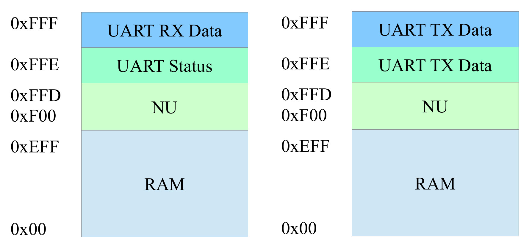
Figure 13 : memory map
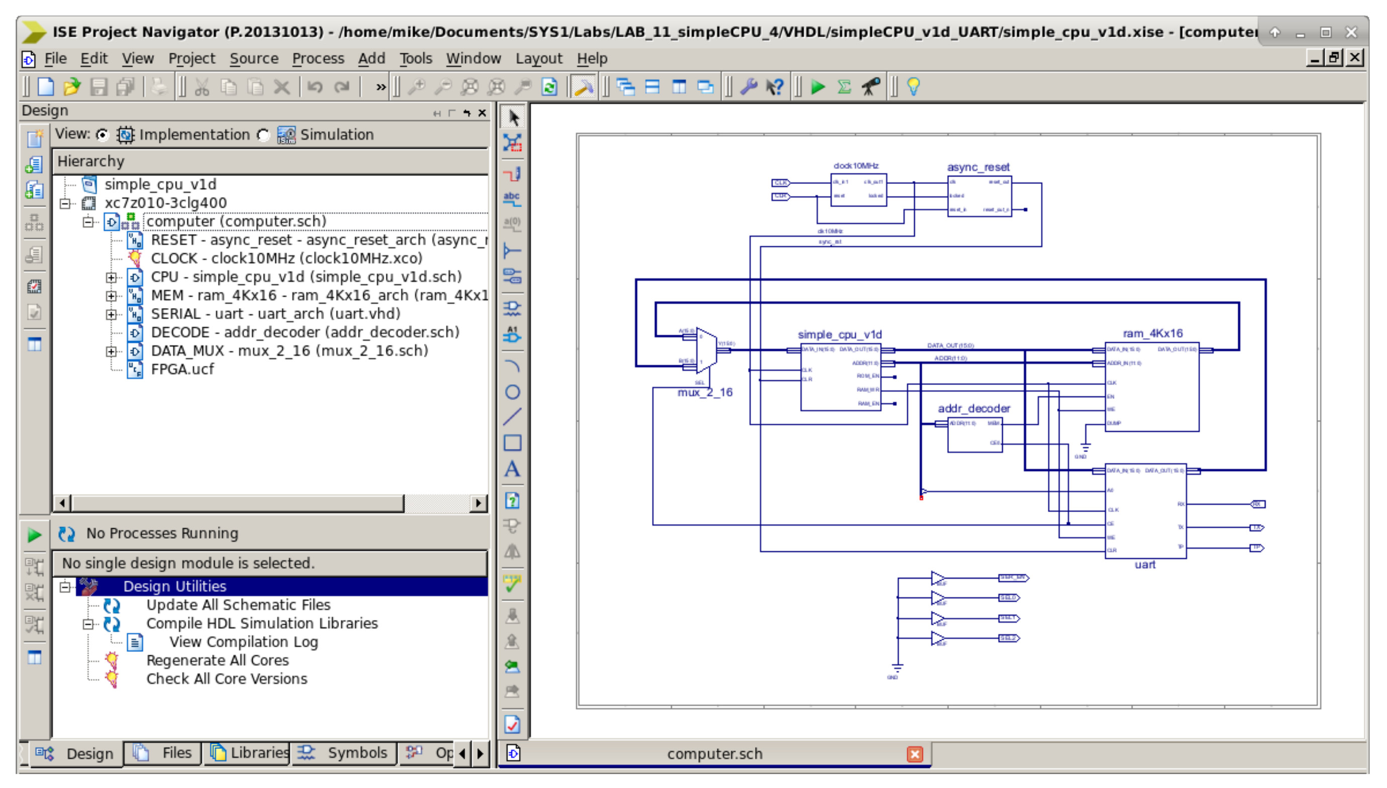
Figure 14 : ISE project
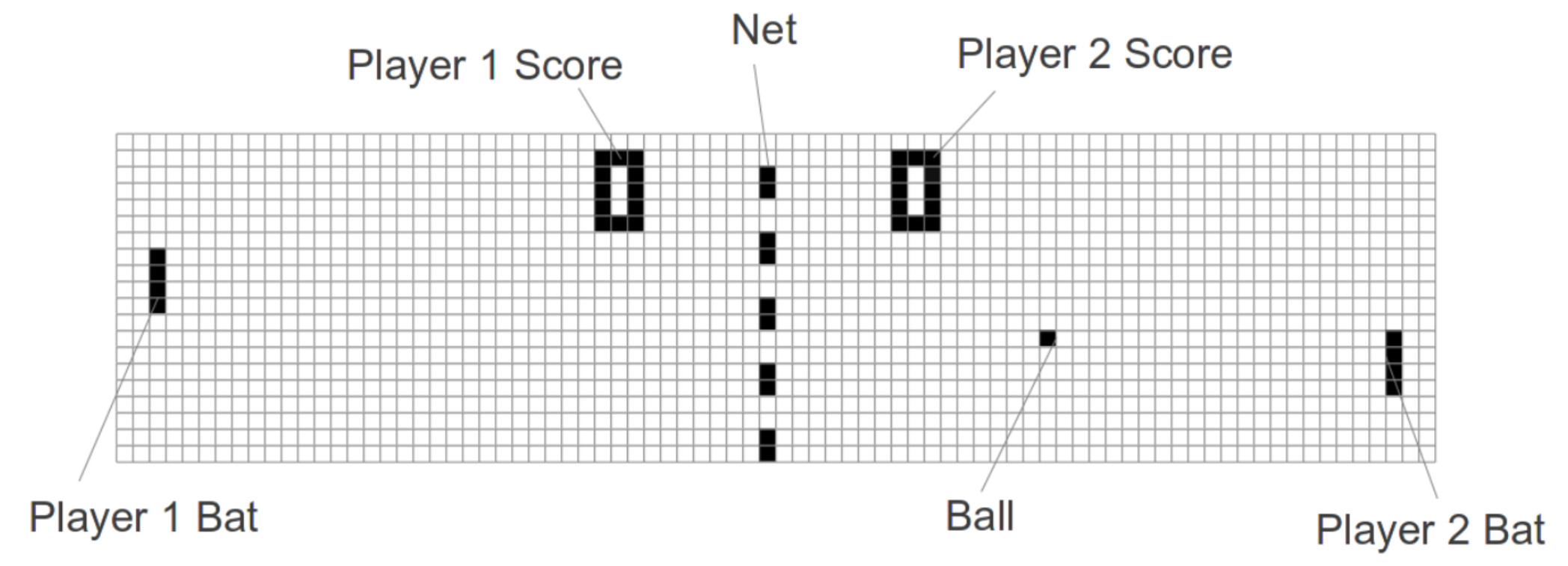
Figure 15 : pong graphics
The default terminal screen size is 80 columns x 30 rows i.e. characters, an initial (approximate) game view is shown in figure 15. Within the display:
The bat stops if it reaches the top (5 pixel) or bottom (24 pixel) display limits. If the ball hits the top or bottom display limits it will bounce off this edge and continue towards the other player. When the ball reaches the left or right display limits (position 10 and 70), if any part of the that player's bat is in 'contact' with the ball the ball will bounce off the bat and travel back to the other player. If ball does not make contact with that player's bat, it will continue through and off the screen. At this point the other player's score is increased by one and service returns to the player that missed. Serves are triggered for both the AI and human player by pressing the "d" key. Each player's score is displayed at the top of the screen, as shown in figure 13. The first player to score ten is the winner. The complete python program can be downloaded here:
To run this program at the command prompt enter: python pong.py.
Note, to simplify testing the "pygame" library was used to implement an OS independent, non-blocking keyboard read i.e. if we used the standard input() function the display will stop updating until a key was pressed. The downside is that you need select the small “graphics” window to enter key presses. Also make sure the command prompt is at least 80 x 30 characters, otherwise word-wrap will cause the screen to update incorrectly.
If all is well you should now be able to play the HD, high FPS, fast action packed game shown in figure 14 :). Remember, you need to select/click-on the small pygame window to enter the key presses.
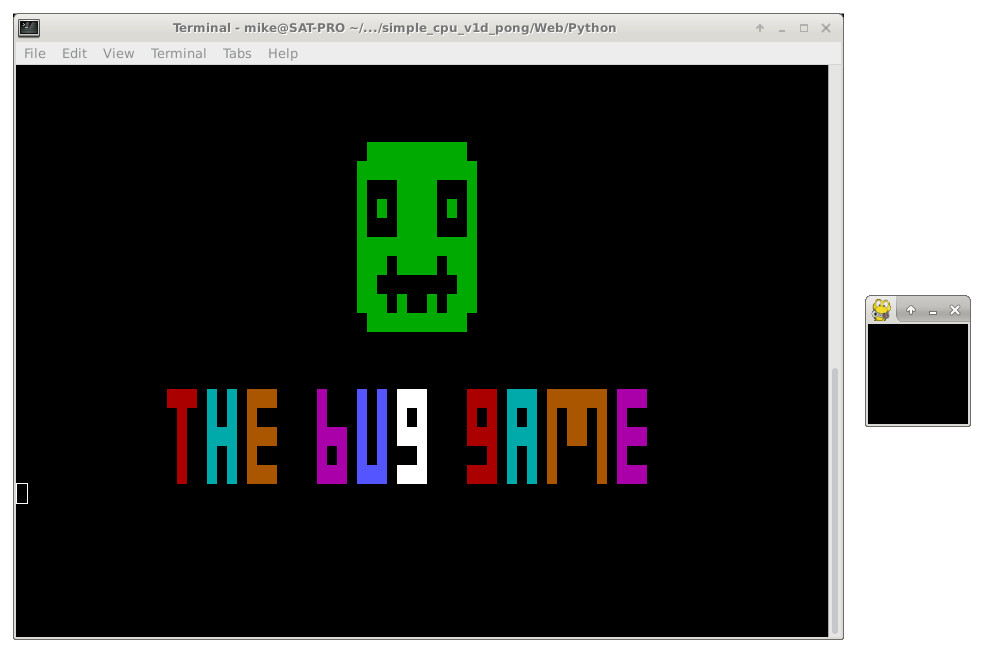

Figure 16 : pong graphics
Now that we have a prototype working in a high level language the next step is to take these ideas a port them to the simpleCPU. The main assembly code loop is shown below:
################
# THE BUG GAME #
################

# MEMORY MAP
# 0xFFF - WR - UART tx
# 0xFFF - RD - UART rx
# 0xFFE - WR - UART tx
# 0xFFE - RD - UART status

# UART REGISTERS
# TX : B7 - B0 data
# RX : B7 - B0 data

# STATUS REGISTER
# B7 : NU
# B6 : NU
# B5 : NU
# B4 : NU
# B3 : NU
# B2 : TX Idle
# B1 : RX Idle
# B0 : RX Valid

# Main
# ----

start:
    call init           # initialise system
    call clear          # clear screen
    call net            # draw net
    call scores         # draw scores
    call ball           # draw ball
    call bat1           # draw user bat
    call bat2           # draw ai bat

loop:
    load RA mode        # serve or play
    and RA 0xFF
    jumpnz play

serve:
    call move_player    # move player
    jump loop

play:
    call move_player    # move player
    call move_ai        # move ai
    call move_ball      # move ball
    call check          # check edges
    call delay          # wait

    jump loop           # repeat

stop:
    jump stop           # trap code for testing
The game's main functions are broken down into a series of subroutines. At the heart of these is a common sprite based draw subroutine. To illustrate this consider the ball drawing subroutine below:
# Draw Ball
# ---------

ball:
    load RA ball_x           # set position
    store RA column
    load RA ball_y
    store RA row

    movea( RA, b_green )     # set colour
    store RA colour

    movea( RA, ball_1 )      # set graphics
    store RA graphics

    call draw                # draw sprite

    ret

ball_1:
    sprite( 0,0,0 )
    sprite( 0,0,0 )
    sprite( 0,1,0 )
    sprite( 0,0,0 )
    sprite( 0,0,0 )
To generate the text string required to draw each sprite the following arguments are passed to the draw subroutine:
# Draw sprite
# -----------

draw:
    move RA 0
    store RA lineCnt         # set sprite line to first
    store RA pixelCnt        # set sprite pixel to first
    store RA colActive       # set colour active to false

    movea( RA, string_buf )
    store RA bufIndex        # set buffer index to start

    movea( RA, b_black )     # get colour string address
    store RA srcAddr         # call strcpy

    load RA bufIndex
    store RA destAddr
    call strcpy
    move RA RC
    store RA bufIndex

draw_next:
    load RA bufIndex
    move RB RA
    move RA 0x1B             # ESC
    store RA (RB)
    add RB 1

    move RA 0x5B             # [
    store RA (RB)
    add RB 1
    move RA RB
    store RA bufIndex

    load RA row              #
    store RA decValue
    call convDecBuf

    load RA bufIndex
    move RB RA
    move RA 0x3B             # ;
    store RA (RB)
    add RB 1
    move RA RB
    store RA bufIndex

    load RA column           #
    store RA decValue
    call convDecBuf

    load RA bufIndex
    move RB RA
    move RA 0x48             # H
    store RA (RB)
    add RB 1
    move RA RB
    store RA bufIndex

    load RA graphics         # load sprite address
    addm RA lineCnt
    move RB RA
    load RA (RB)             # load pixel data
    store RA line            # buffer line

draw_loop:
    load RA line
    and RA 0x04              # test bit position
    jumpz draw_black

draw_colour:
    load RA colActive        # is colour active
    and RA 0xFF
    jumpnz draw_colourSet

    move RA 1                # set colour is active flag
    store RA colActive
    load RA colour           # get colour string address
    store RA srcAddr         # call strcpy
    load RA bufIndex
    store RA destAddr
    call strcpy
    move RA RC
    store RA bufIndex

draw_colourSet:
    load RA bufIndex         # draw block (space)
    move RB RA
    move RA 0x20
    store RA (RB)
    add RB 1
    move RA RB
    store RA bufIndex
    jump draw_nextPixel

draw_black:
    load RA colActive
    and RA 0xFF
    jumpz draw_blackSet

    move RA 0                # set colour is not active flag
    store RA colActive

    movea( RA, b_black )     # get colour string address

    store RA srcAddr         # call strcpy
    load RA bufIndex
    store RA destAddr
    call strcpy
    move RA RC
    store RA bufIndex

draw_blackSet:
    load RA bufIndex         # draw block (space)
    move RB RA
    move RA 0x20
    store RA (RB)
    add RB 1
    move RA RB
    store RA bufIndex

draw_nextPixel:
    load RA line             # move to next pixel
    asl RA
    store RA line
    load RA pixelCnt         # inc pixel count
    add RA 1
    store RA pixelCnt
    sub RA 3
    jumpnz draw_loop

    move RA 0                # zero pixel count
    store RA pixelCnt
    load RA row              # move to next row
    add RA 1
    store RA row
    load RA lineCnt          # inc line count
    add RA 1
    store RA lineCnt
    sub RA 5                 # have all 5 rows been processed?
    jumpnz draw_next

    load RA bufIndex         # yes, insert NULL
    move RB RA
    move RA 0x0
    store RA (RB)

    call txString            # display string

    ret
The draw subroutine constructs the required text string in the array string_buf in memory to draw the request sprite. When complete this buffer is then transmitted to the host PC across the serial link via the UART. As part of this process the row and column values at which the sprite is drawn need to be converted into decimal characters as defined by the ANSI Set Graphic Rendition (SGR) command codes. To convert the simpleCPU's binary values into decimal characters the convDefBuf subroutine is used:
# Convert variable DECVALUE into decimal characters
# -------------------------------------------------
# Used in cursor movement commands RANGE limited to 99 - 0

convDecBuf:
    load RA bufIndex
    move RD RA
    load RA decValue
    move RB 0

convDecBuf_H:
    sub RA 10                # sub 10
    move RC RA               # copy for compare
    and RC 0x80              # neg?
    jumpnz convDecBuf_HTx    # yes, exit
    add RB 1                 # inc count
    jump convDecBuf_H        # repeat

convDecBuf_HTx:
    add RA 10                # undo last sub
    move RC RA               # buffer for units
    and RB 0xFF              # skip if 10s count 0
    jumpz convDecBuf_LTx

    move RA RB               # copy count
    add RA 0x30              # convert to ASCII
    store RA (RD)
    add RD 1

convDecBuf_LTx:
    move RA RC               # copy count
    add RA 0x30              # convert to ASCII
    store RA (RD)
    add RD 1
    move RA RD
    store RA bufIndex

    ret
A significant amount of the processing time involved in generating the required text string is copying the selected escape sequences into the string_buf buffer. This is done using the strcpy subroutine:
# Copy string (must terminate with a \0)
# --------------------------------------
# Source / destination addresses passed in SRCADDR / DESTADDR

strcpy:
    load RA srcAddr          # get source address
    move RB RA
    load RA destAddr         # get destination address
    move RC RA

strcpy_loop:
    load RA (RB)             # load  char
    and RA 0xFF
    jumpz strcpy_exit        # exit if 0
    store RA (RC)            # copy
    add RB 1
    add RC 1
    jump strcpy_loop         # repeat

strcpy_exit:
    ret
When the TX buffer string_buf contains the final escape sequences these are transmitted to the host PC using the txstring subroutine:
# TX String (must terminate with a \0)
# ------------------------------------
# Base address passed in variable STRING

txString:
    movea( RB, string_buf )  # get string address

tx_loop:
    load RA (RB)             # load  char
    and RA 0xFF
    jumpz tx_exit            # exit if 0
    store RA TXCHAR          # tx

waitTX:
    load RA STATUS           # test TX status wait till 1
    and RA 0x04
    jumpz waitTX

    add RB 1                 # inc address
    jump tx_loop             # repeat

tx_exit:
    ret
 )
With a few slight variations on this theme and a basic state machine to control the different phases of the game we can implement a simpleCPU version of Pong. To display the escape sequences on the PC, open a terminal window, resize to at least 80 x 30 to avoid word wrap, then enter:
screen /dev/ttyUSB0 19200
Screen shots of the game running are shown in figure 17. A short video of the game in action is available here (Link).
Note, to exit screen press CTL+a, then k, then answer yes. Confess its a little slow on the screen update, but this was due to the RS232 to USB serial port adapter's max speed being limited to 19200 bps. Could of easily got a x8 increase in screen fps if i had bought the more expensive 115200 bps version :(.
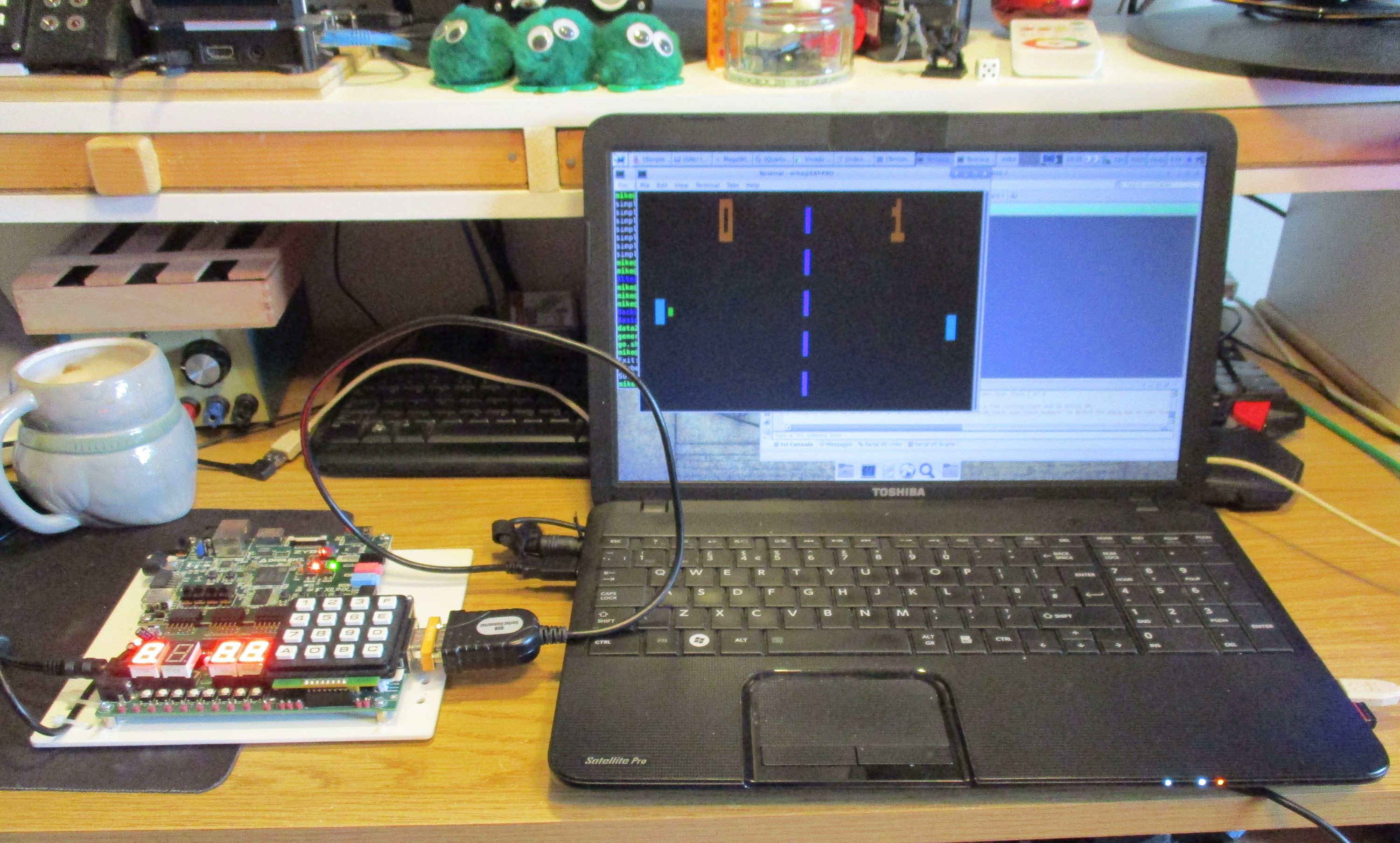
Figure 17 : Xilinx pong game
The lab FGPA boards are Xilinx based, good functionality, but the downside is that they are a little on the expensive side. However, i found a cheap Altera FPGA board online: Altera FPGA Cyclone ll EP2C5T144 Development Board. This board (£15), plus its USB programming cable (£8), came to approximately £21, shown in figure 18. Therefore, i decided to port the simpleCPU pong game to this new board.
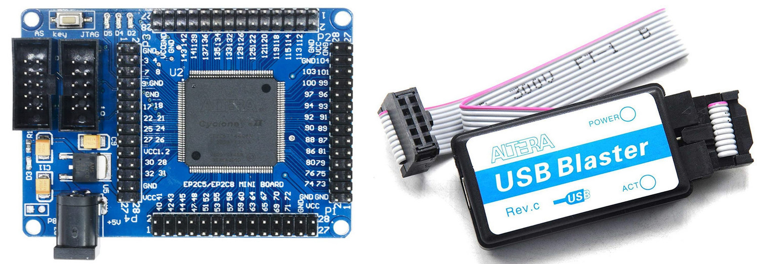
Figure 18 : Altera Cyclone ll FPGA EP2C5T144 development board (left), USB Blaster JTAG Download Cable Debugger (right)
This minimal developed board only has GPIO pins, so to implement the RS232 interface i used the USB to TTL Serial Debug Cable shown in figure 19, costing approximately £4. This cable has four pins: Red +5V, Black GND, Green TXD, White RXD. The USB adapter is a PL2303, it doesn't seem to work / has "issues" under windows, but is fine in Linux. I did have a Google around, there seems to be some discussion about using an older driver, but as it worked under Linux i didn't want to mess up my windows box.

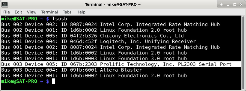
Figure 19 : USB to TTL Serial Debug Cable
To program this FPGA use Quartus II 13.0sp1 Web Edition (Link). Note, there are newer versions of Quartus, but these do not support the Cyclone II chipset. This software is similar to the Xilnx ISE environment allowing schematic and HDL design entry, but as you would expect you can't import the Xilinx schematics :(. Therefore, i decided to manually convert the schematic into a VHDL representation to simplify the transition to this new FPGA i.e. define the processor and its peripherals using generic VHDL models. As always the one exception to this plan is the memory. As with Xilinx designs these need to be mapped to the FPGA specific memory cores. For Xilinx these are RAMB16_S4 block rams (Link) and for Altera M4K memory blocks (Link). To generate the Altera's memory i used the Mega Wizard plug-in manager as shown in figure 20.
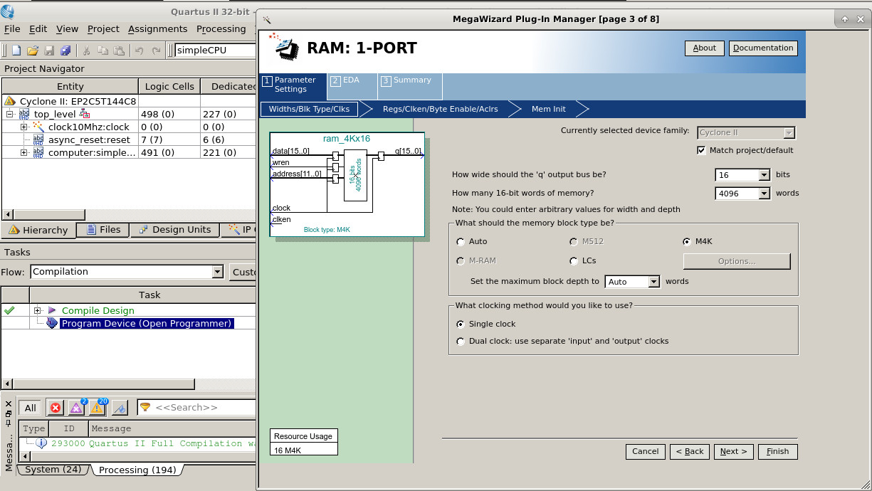
Figure 20 : M4K memory block
Unfortunately these memory devices are slightly different from the original ones used in the Xilinx FPGAs :(. Both FPGAs use synchronous memory devices, but the Altera's FPGA memory has an additional output buffer stage (registered) i.e. memory timings are different, the Altera memory blocks taking an additional clock cycle. Note, this problem is due to how the simpleCPU operates, the Altera FPGA memory is just as fast as the Xilinx FPGA, but its intended for pipeline operations, unfortunately the simpleCPU was not designed to operate in this way. Therefore, this timing problem messes up the fetch and execute phases on the simpleCPU. We could overcome these issues by modifying the simpleCPU's architecture i.e. the number of clock cycles needed for instructions that access operands from memory (LOAD, STORE, ADDM and SUBM). That would be a pain and i don't want to start modifying the simpleCPU's internals for different FPGA's. Therefore, bodge :). To get the same functionality i used a phase lock loop (PLL) on the Altera FPGA to generate two different clocks, the standard 10MHz system clock and a 20MHz clock, with a 90 degree phases shift, as shown in figure 21.
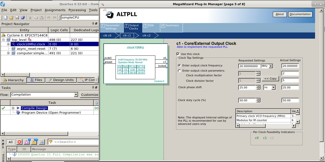
Figure 21 : PLL 20MHz clock parameters
The CPU is runs at 10MHz and the memory now runs at 20MHz, it still takes an extra clock cycle to get the data from the memory, but as its running twice as fast, from the CPU's point of view it's all good. Yes i know a bodge, but it works :), a final compiled top_level design is shown in figure 22.
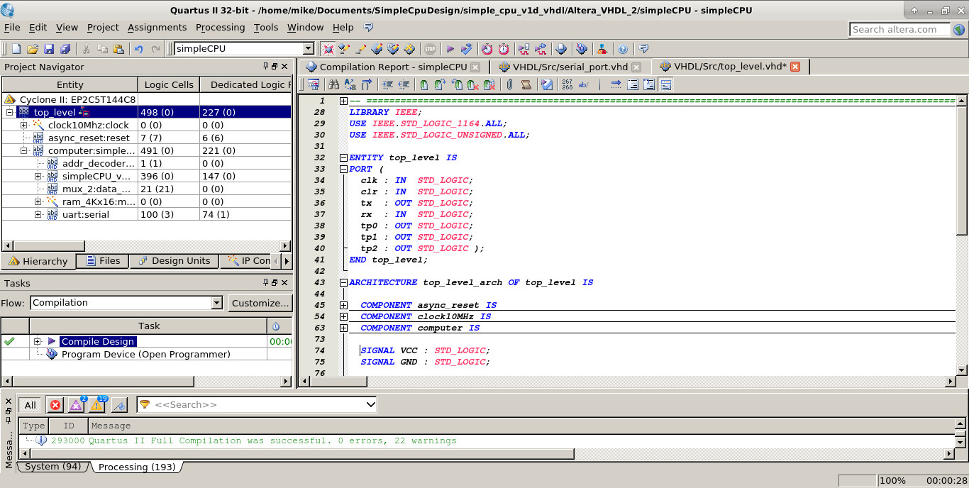
Figure 22 : top_level Quartus II project
Screen shots of the game running are shown in figure 23. A short video of the game in action is available here (Link).
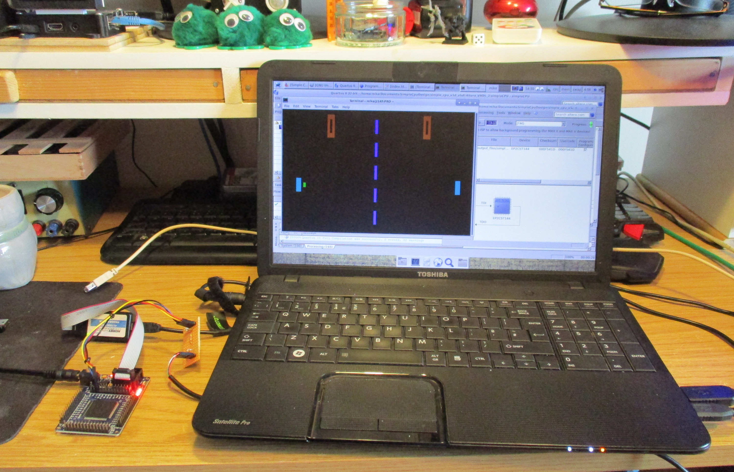
Figure 23 : Altera pong game
Both FPGA boards use a 3.3V IO standard, therefore, the +5V signal from the USB to TTL serial debug cable to the FPGA board need to be shifted down to this level. Signals from the FPGA to the USB to TTL serial debug cable are ok as 3.3V signals will still be interpreted as a logic 1. You can buy specific level shifter ICs to implement these functions, however, for this system a simple resistor circuit will suffice, as shown in figures 24 and 25.
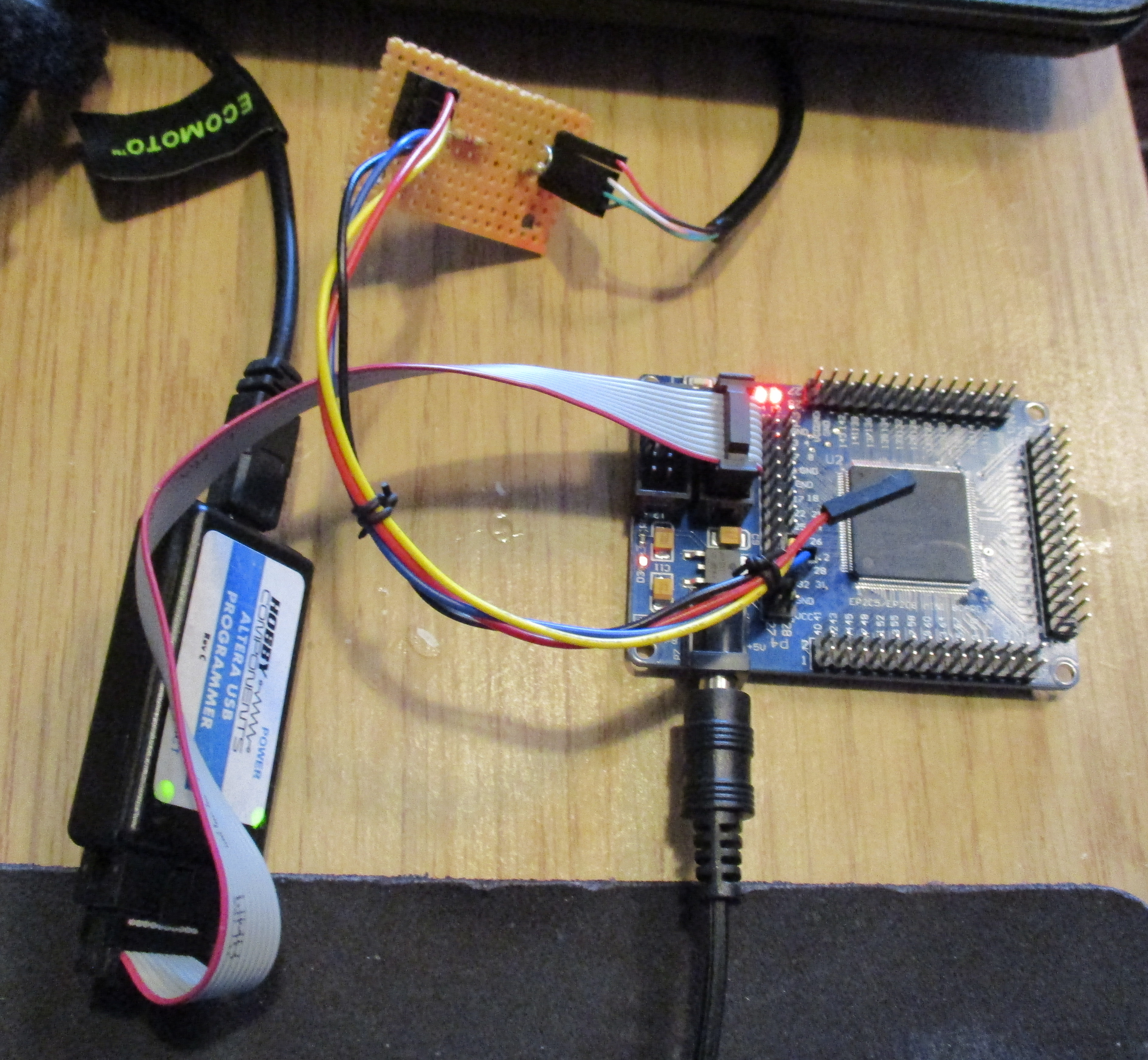
Figure 24 : Altera FPGA board
This circuit is a simple potential divider, halving the TX signal from the USB to TTL serial cable.
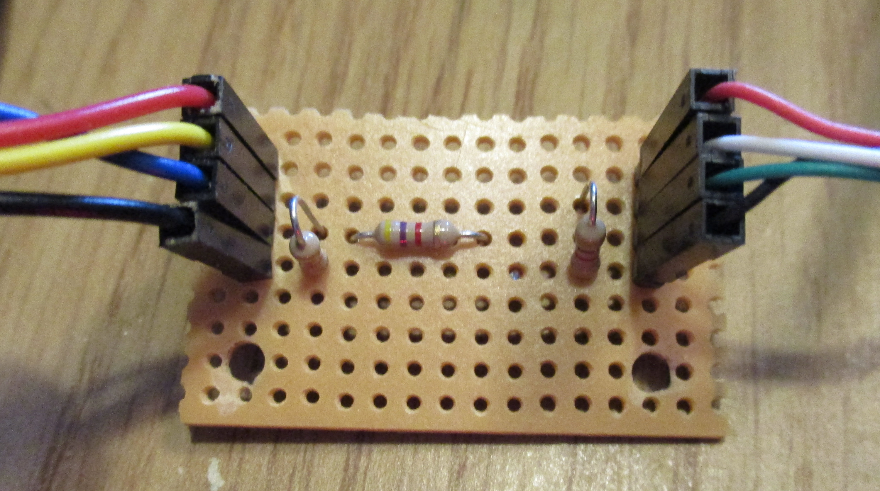
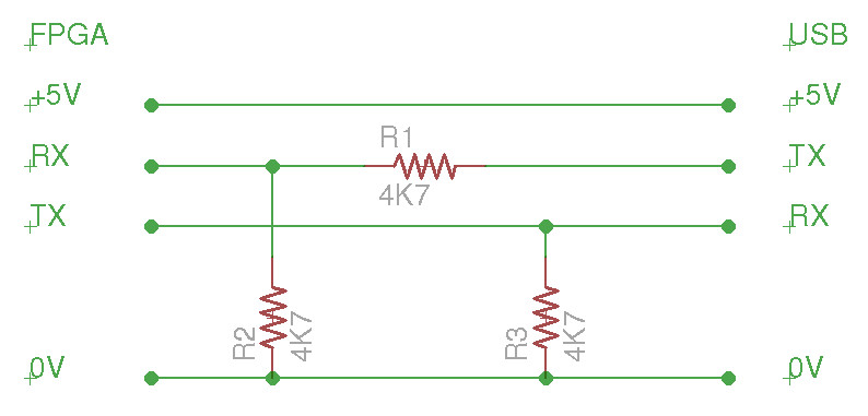
Figure 25 : Level shifter
Work done for the present. As previously discussed the next version will be a hand held implementation.
WORK IN PROGRESS

This work is licensed under a Creative Commons Attribution-NonCommercial-NoDerivatives 4.0 International License.
Contact email: mike@simplecpudesign.com