
Figure 1 : New servers, or Deep-thought?
Continuing the journey that is teaching "an introduction to networking", well for one more year, next year i believe changes are a foot :(, change is bad :). Anyway, i need to make some space and all the separate Pi servers that currently live on my windowsill in my office and they need to move, sooooo a rebuild, as shown in figure 1. Note, i think this server tower has a passing resemblance to the Hitchhiker's Guide to the Galaxy Deep-thought computer (Link), the one from the BBC TV series. Well the LED display is green :). This tower contains the six Raspberry Pi servers used on the labs network:
In addition to the above servers we also have our standalone servers from last time:
Case and power supply.
NTP server.
DNS server.
FTP server.
SMTP server
DOCKER server.
IRC server.
The new server build is based on / inspired by some old thin-client boxes i found in our e-waste bin, as shown in figure 2. I think these are old Intel Atom based machines. I did initially think of using these, but with IDE drives and no SATA or USB, i decided that this approach was perhaps toooo much fun. However, they do have a nice metal case and a +12V to +5V power supply with enough poke to power a couple of Raspberry Pis. Soooo, the plan is to have an upgrade, replace the old Pi-2 based servers with Pi-4 boards and mount these in these cases. I can fit two Pi per case, so with three boxes, that will give me six Pis, with 24-cores of processing power :).
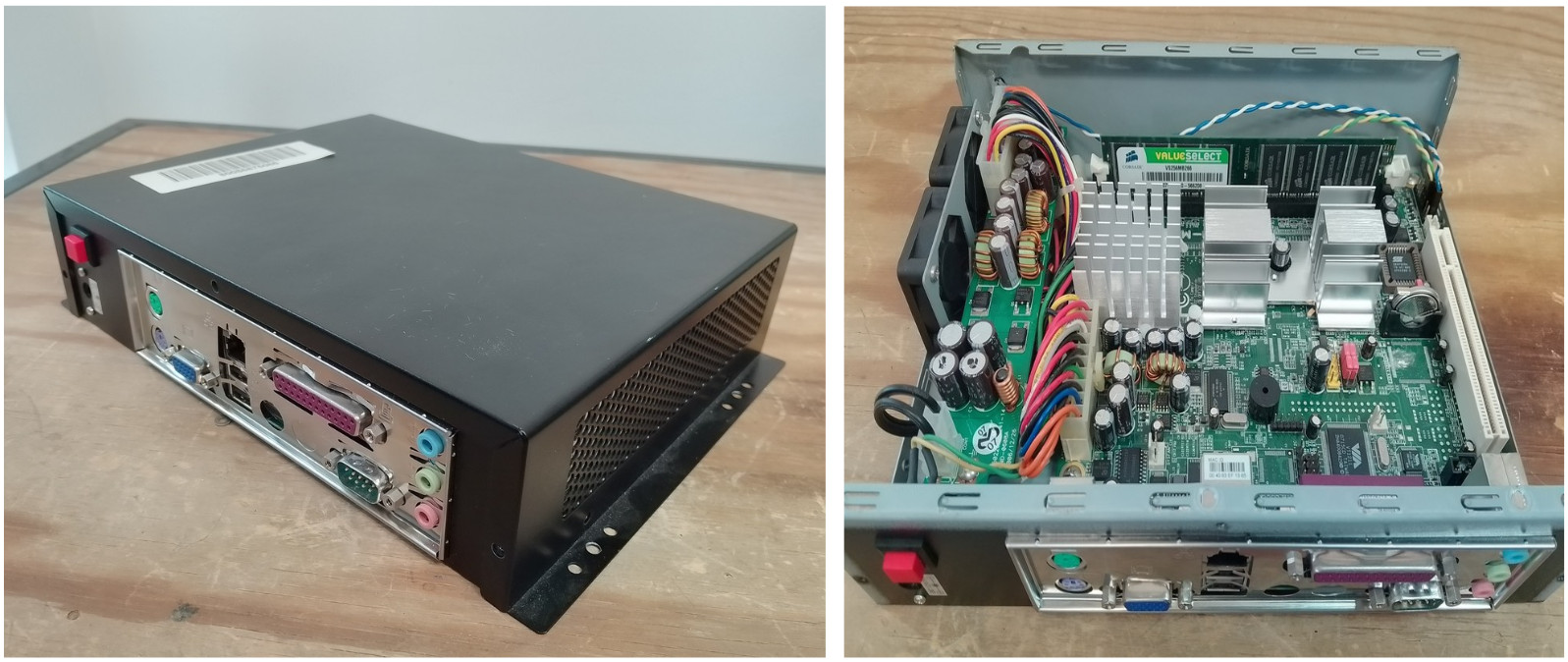
Figure 2 : Thin-client
These old thin-client cases work off an external 12V, 5A power supply. Soooo, if a no load Pi-4 takes around 500mA (or less) and a full load Pi takes around 1.5A (or more), this in theory gives us a power requirement for 6 x Pi4 of:
IDLE Power = 6 x 0.5 = 3A = 5V x 3 = 15W
FULL Power = 6 x 1.5 = 9A = 5V x 9 = 45W
POWER Supply = 12V x 5A = 60W
Sooo, in theory all six boxes can be powered from one power supply. A nice feature of these boxes is that they already support chaining, having a power-in DC jack (2.5mm) 12V and a power-out DC jack (2.1mm) 12V. Inside the case there is a switch mode power supply that converts the +12V into your normal PC power supply outputs, as shown in figure 3.
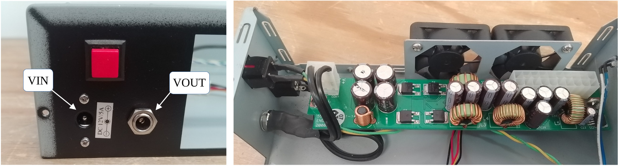
Figure 3 : PC power supply connector
To "turn on" this power supply board i.e. enable its outputs, you need to connect the PS_ON# (green wire) pin to 0V (black wire), as "shown" in figure 4. In the past i think i remember someone telling me you also had to have some form of load on the +5V supply to enable the different regulators, however, it all seemed to work with no load. For this application i am only using the +5V output for the Pi and the +12V for the fans. Therefore, the +3.3V, -5V and -12V are not used.

Figure 4 : PC power supply
To connect this power suuply to the Pi i found some pre-wired USB-C power leads on Amazon, shown in figure 5. The cable a little on the thin side, but a lot easier than cutting up USB-C cables.
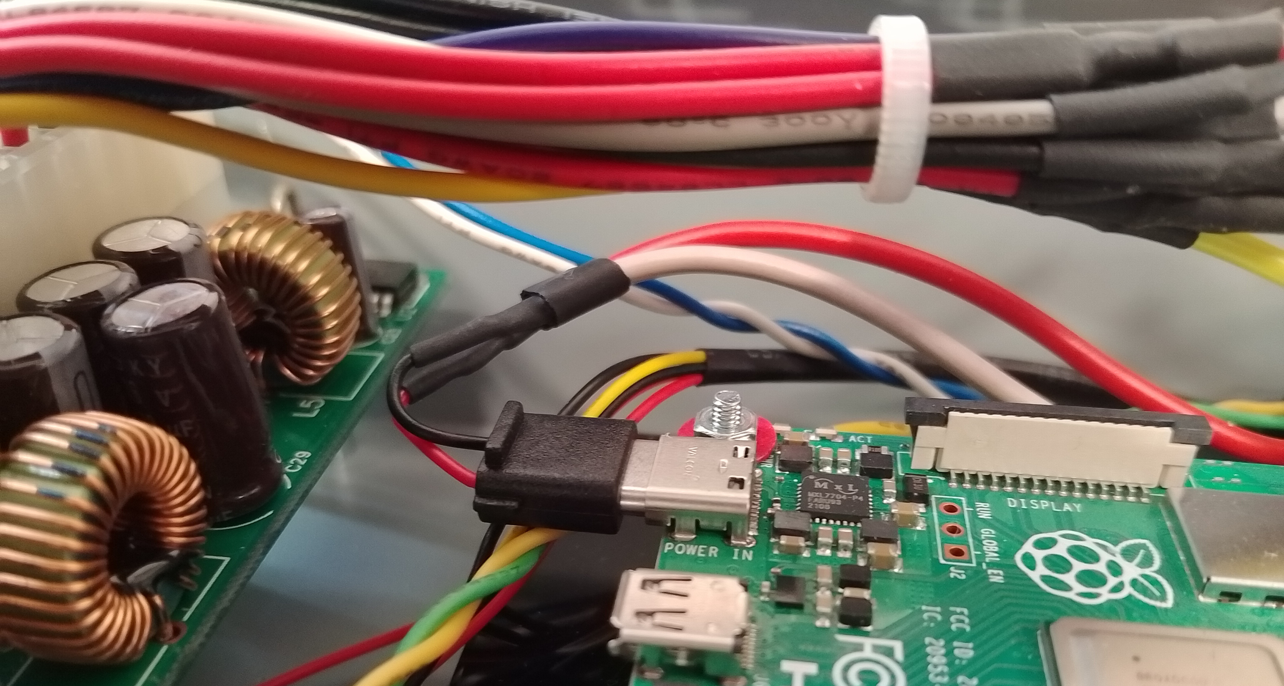
Figure 5 : Pi power +5V
The case also has a reset switch, a RED push switch mounted on the back and a front mounted power LED, a blue LED, for the time a rare thing. Note, in the pictures the reset switch uses GREEN/YELLOW wires and LED BLUE/WHITE wires. This push switch is connected to each Pi, GPIO pin-21 and is used to trigger the shutdown command. As there are two Pi in a case this reset signal is split i.e. same signal is connected to each Pi.
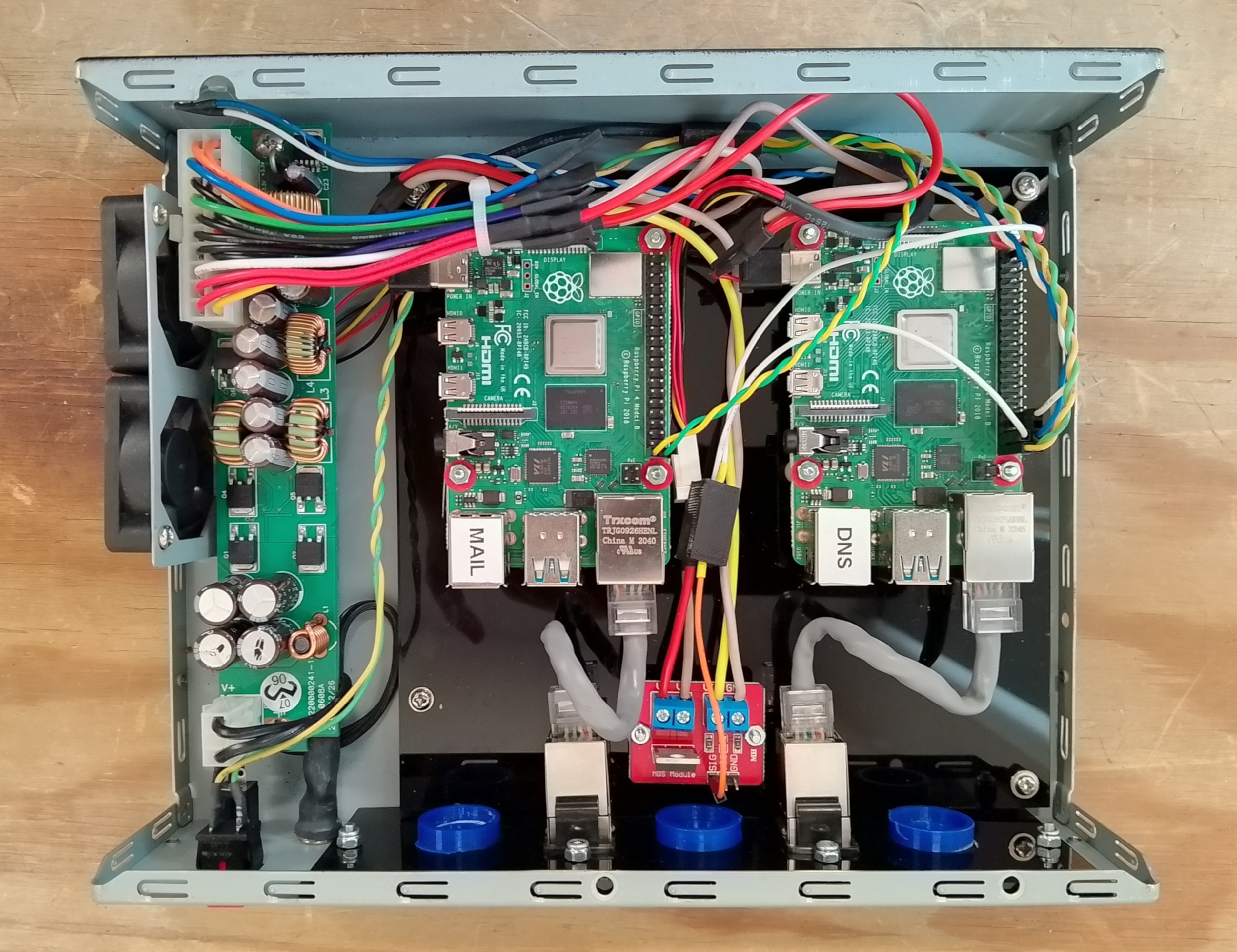
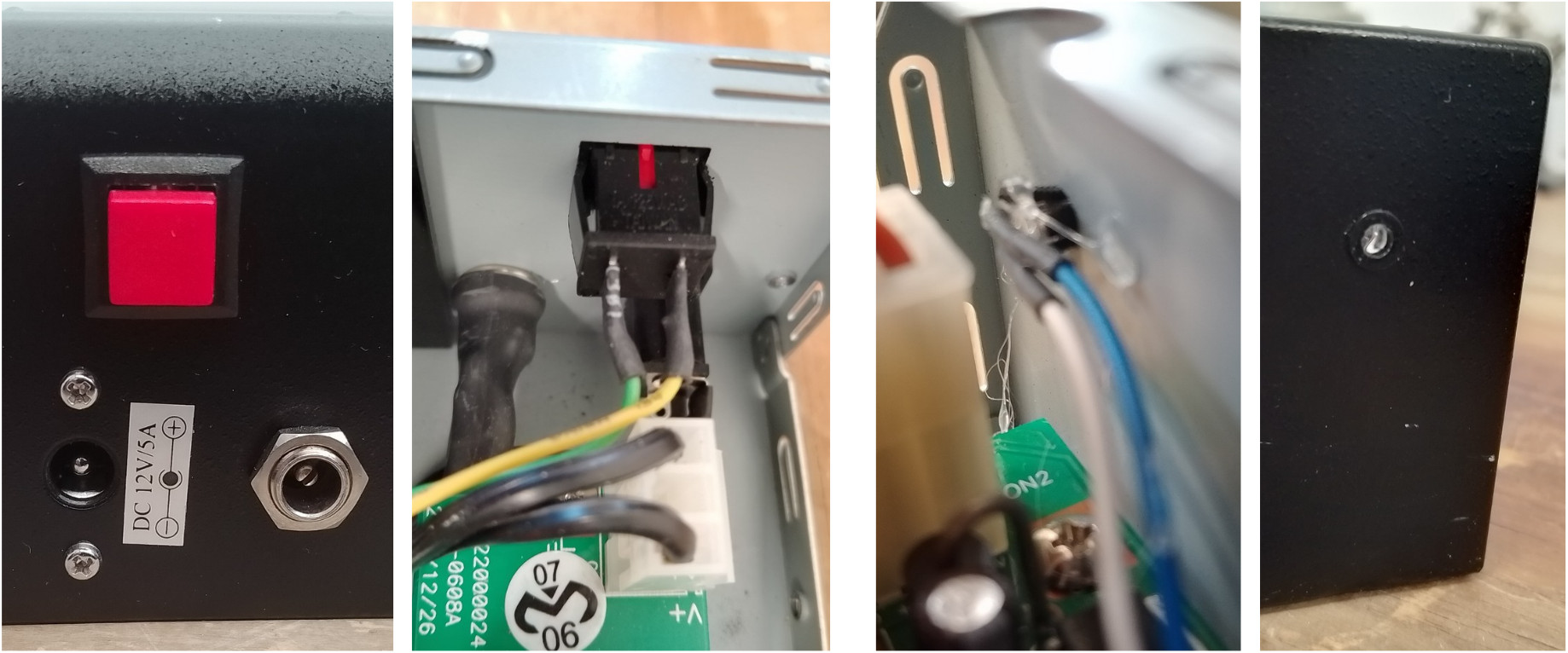
Figure 6 : Shutdown button (left), Power LED (right)
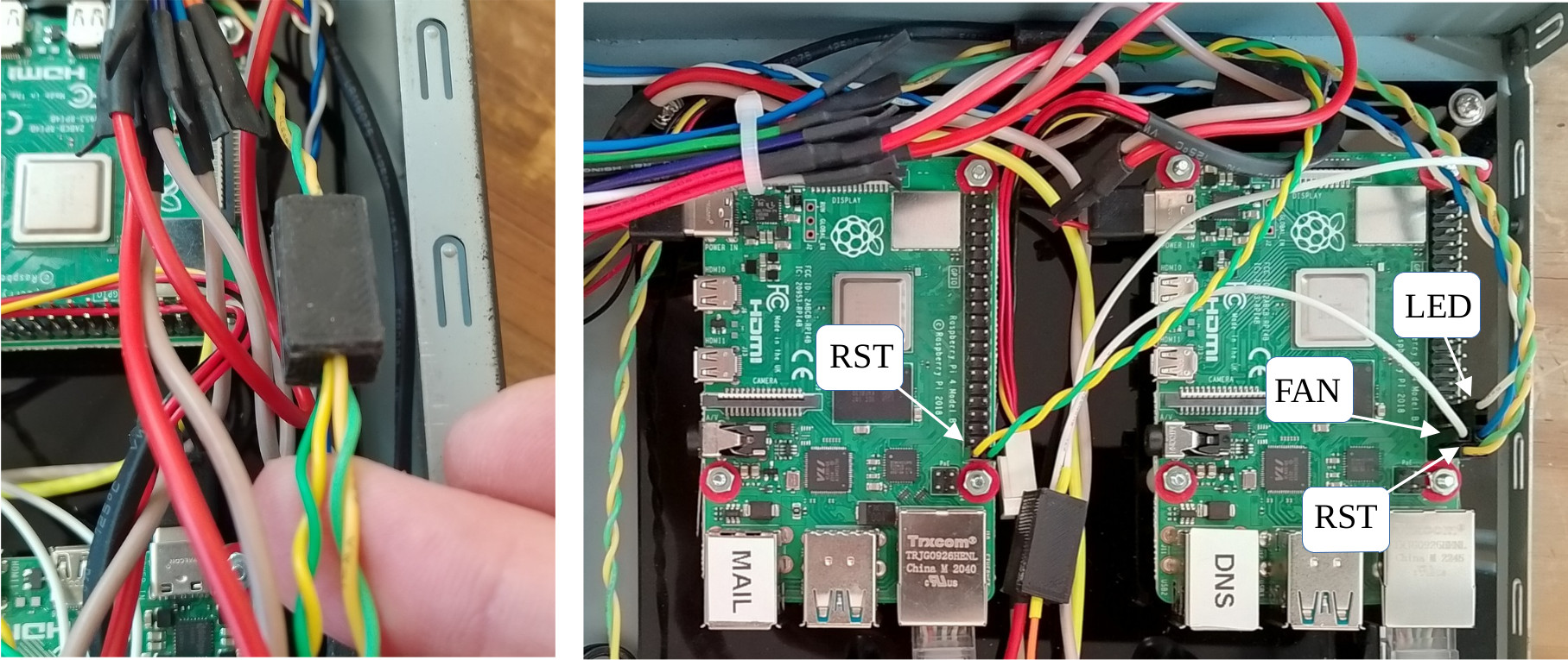
Figure 7 : Shutdown wiring
To hide the join (heatshrink) caused by the shutdown signal split i 3D printed some small boxes, as shown in figure 8. These are particularly useful if you need to hide a few components / wires etc. You can download the STL for these boxes here: (Link).

Figure 8 : Wiring boxes
I have used this approach to shutdown a Pi on a number of different systems i.e. a GPIO pin with internal PullUp, connected to a push button that connects this pin to GND. For convenience i tend to use pins 39 and 40 i.e. GND and GPIO-21, at the bottom of the header, as you can use a 2 pin 0.1 pitch connector. However, in this setup there seems to be a bit of a noise issues, causing the Pis to shutdown randomly. Note, this is infrequent, but a definite issue, confess not sure what is causing this :(.

Figure 9 : Pi GPIO header
Ideally i would add some denounce, an RC network on this signal, to filter out this noise, but that would mean adding more wiring, a small PCB, soldering ..., so decided to bodge it :) and updated the shutdown code to :
import RPi.GPIO as GPIO
import time
import os

from datetime import datetime

def log(message):
    timestamp = datetime.now().strftime("%Y-%m-%d %H:%M:%S")
    print(f"[{timestamp}] {message}")

GPIO.setmode(GPIO.BCM)
GPIO.setup(21, GPIO.IN, pull_up_down=GPIO.PUD_UP)
GPIO.setup(20, GPIO.OUT)
GPIO.output(20, True)

try:
    log(" : Start")
    while True:
      GPIO.wait_for_edge(21, GPIO.FALLING)

      count=0
      for i in range(0, 7):
        time.sleep(0.1)
        if GPIO.input(21) == GPIO.LOW:
          count = count + 1

      if count == 7:
        for i in range(0, 5):
          GPIO.output(20, False)
          time.sleep(0.5)
          GPIO.output(20, True)
          time.sleep(0.5)

        log(" : Stop")
        os.system("sudo shutdown -h now")
except:
    pass
GPIO.cleanup()
Now after the initial event, the GPIO pin is sampled 7 times, every 0.1s i.e. for a second-ish. If this GPIO pin remains low for that time the Pi is shutdown, otherwise its considered noise and ignored. I know its a bodge, but these "noise" events are infrequent, and this bodge does seems to work, but we shall see.
I could have connected the power LED to the +3.3V on one of the Pi. I did consider making some sort of diode based AND gate, so that the LED only came on if both Pis were powered. However, in the end i decided on a "soft" power LED, again controlled by the above code. The LED is connected to pins 38 and 34 i.e. GPIO-20 and GND, you need a 330 ohm current limiting resistor in line with one of the wires, either is fine. I forgot to take a photo so figure 10 is an artist impression of this circuit :). The above code turns on the LED when the Pi has booted. When the Pi is shutdown by the RED push button the LED will flash five times to signal that the shutdown button was pressed before turning off. Note, the LED is only connected to one of the Pis.

Figure 10 : Power LED wiring box hiding 330 ohm resistor
The final box related item are the fans. Originally these were controlled by motherboard, sooo i assume that the PSU does not need forced cooling i.e. there is no signal from the PSU to the motherboard to signal that the fans need to be turned on. So i've taken the same approach here. Wrote some python code to read the Pi temperature and turn on the two +12V fans using a simple n-type MOSFET driver board, as shown in figure 11.

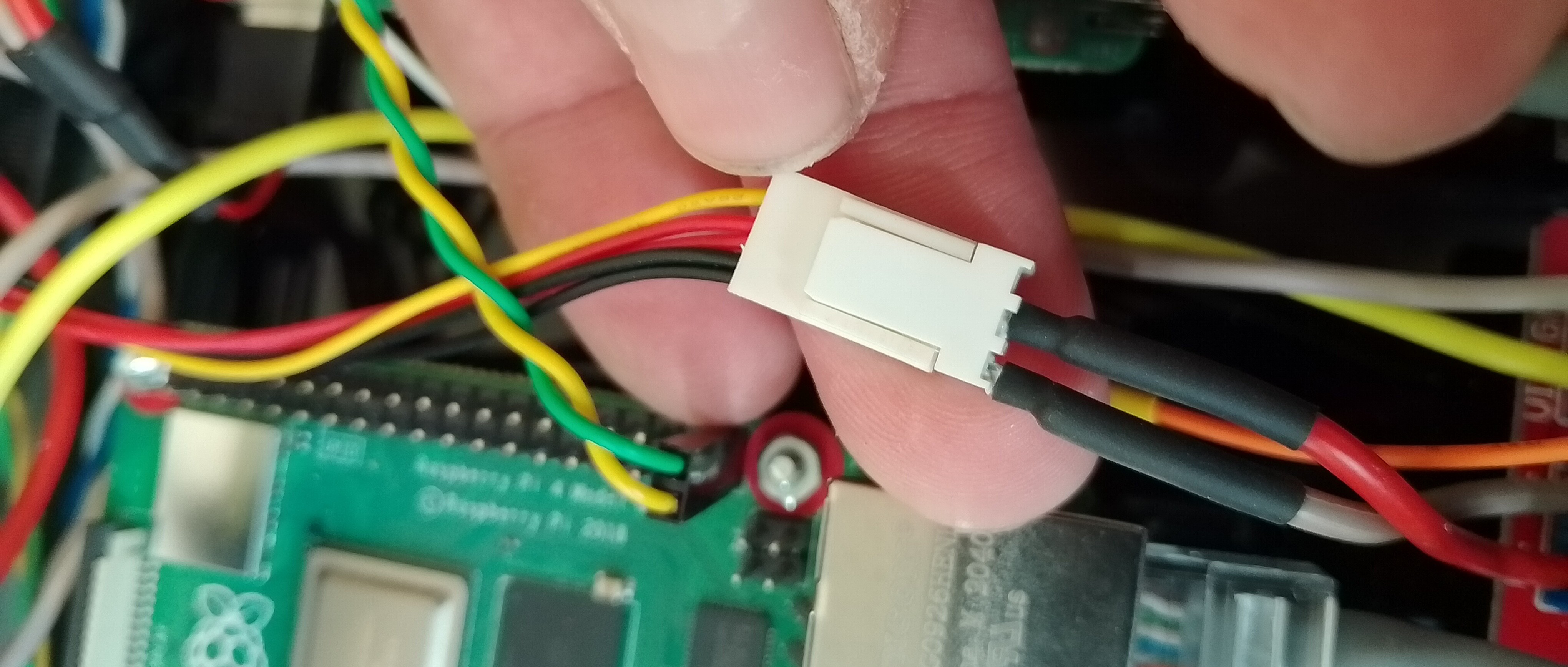
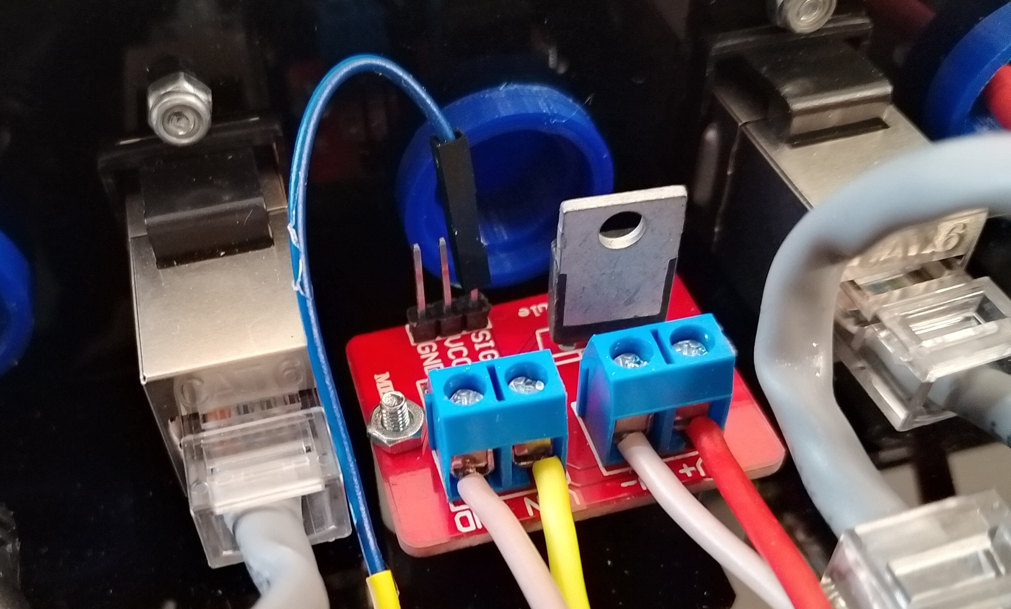
Figure 11 : Fans (top), wiring (middle), MOSFET driver (bottom)
In theory this should have been a very simple task :(, however, i decided to simplify things by buying an off the shelf MOSFET driver board from Amazon :(. Sooo, the gate threshold voltage of the MOSFET used on this board was tooo high, not suitable for the Pi's 3.3V GPIO i.e. the MOSFET used had a standard VGS threshold of 2V to 4V, rather than the required VGS threshold of 1V to 2V. Note, the VGS threshold is the voltage at which the MOSFET starts conducting. As a result the fans would not turn on, the MOSFET was simply not switched on enough to pass the required current. Sooo bodge number 2, remove the 4.7K ohm pulldown resistor on the PCB (strange value, a little low) and add a 330 ohm pullup resistor in the wiring box. Then change the python code to not use 0V and 3.3V, but rather 0V and high impedance. Therefore, when the GPIO line switched to the high impedance state the output will be pulled up to +5V via the 330 ohm resistor. Note, i selected the lowest value i felt happy with to increase switching speed i.e. overcome any capacitance, RC delay. The side affect of this is that there will be current flowing into this pin via the Pi's protection diodes i.e. ((5-3.3)-0.7)/330, but that should be within the Pi's spec. Code and "artists" impression of wiring below.
import os
import time
import RPi.GPIO as GPIO
from datetime import datetime

# --- Configuration ---
TEMP_THRESHOLD = 50.0        # Degrees Celsius
GPIO_PIN = 26                # BCM pin number
CHECK_INTERVAL = 60          # Seconds between updates

# --- Setup GPIO ---
GPIO.setmode(GPIO.BCM)
GPIO.setwarnings(False)
GPIO.setup(GPIO_PIN, GPIO.OUT)
GPIO.output(GPIO_PIN, GPIO.LOW)

def get_cpu_temp():
    try:
        with open("/sys/class/thermal/thermal_zone0/temp", "r") as f:
            temp_str = f.read()
            return float(temp_str) / 1000.0  # Convert millidegrees to degrees
    except FileNotFoundError:
        log(" : Temperature file not found.")
        return None

def log(message):
    timestamp = datetime.now().strftime("%Y-%m-%d %H:%M:%S")
    print(f"[{timestamp}] {message}")

try:
    log(" : Starting temperature monitor...")
    while True:
        temp = get_cpu_temp()
        if temp is not None:
            #log(f" : Current CPU Temp: {temp:.2f}°C")
            if temp > TEMP_THRESHOLD:
                #GPIO.output(GPIO_PIN, GPIO.HIGH)
                GPIO.setup(GPIO_PIN, GPIO.IN, pull_up_down=GPIO.PUD_UP)
                log(" : Temp above threshold! Turn on fans")
            else:
                GPIO.setup(GPIO_PIN, GPIO.OUT)
                GPIO.output(GPIO_PIN, GPIO.LOW)
                log(" : Temp below threshold. Turn off fans")
        time.sleep(CHECK_INTERVAL)

except KeyboardInterrupt:
    log(" : Stopping monitor...")
finally:
    GPIO.cleanup()
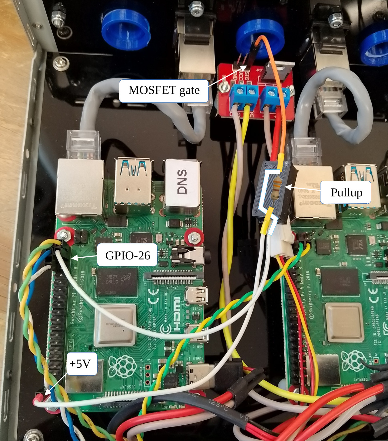
Figure 12 : pullup resistor
In action the Pi reads its core temp every minute, if above 50 degrees it turns on the fan and repeats. Note, key thing here is to not write a program that switches this control signal too quickly i.e. at processor speed, need a delay in seconds, otherwise things may go pop. This circuit is not designed to implement a PWM controller, just basic on and off control. Note, have not fitted heatsinks to the Pis at the moment, working temp is around 48 degrees, which i thought was fine, fans kick in now and then so i don't think heat will be an issue.
Finally, for those that need them and for me when i loose them the remaining DXF and STL files used in this design:
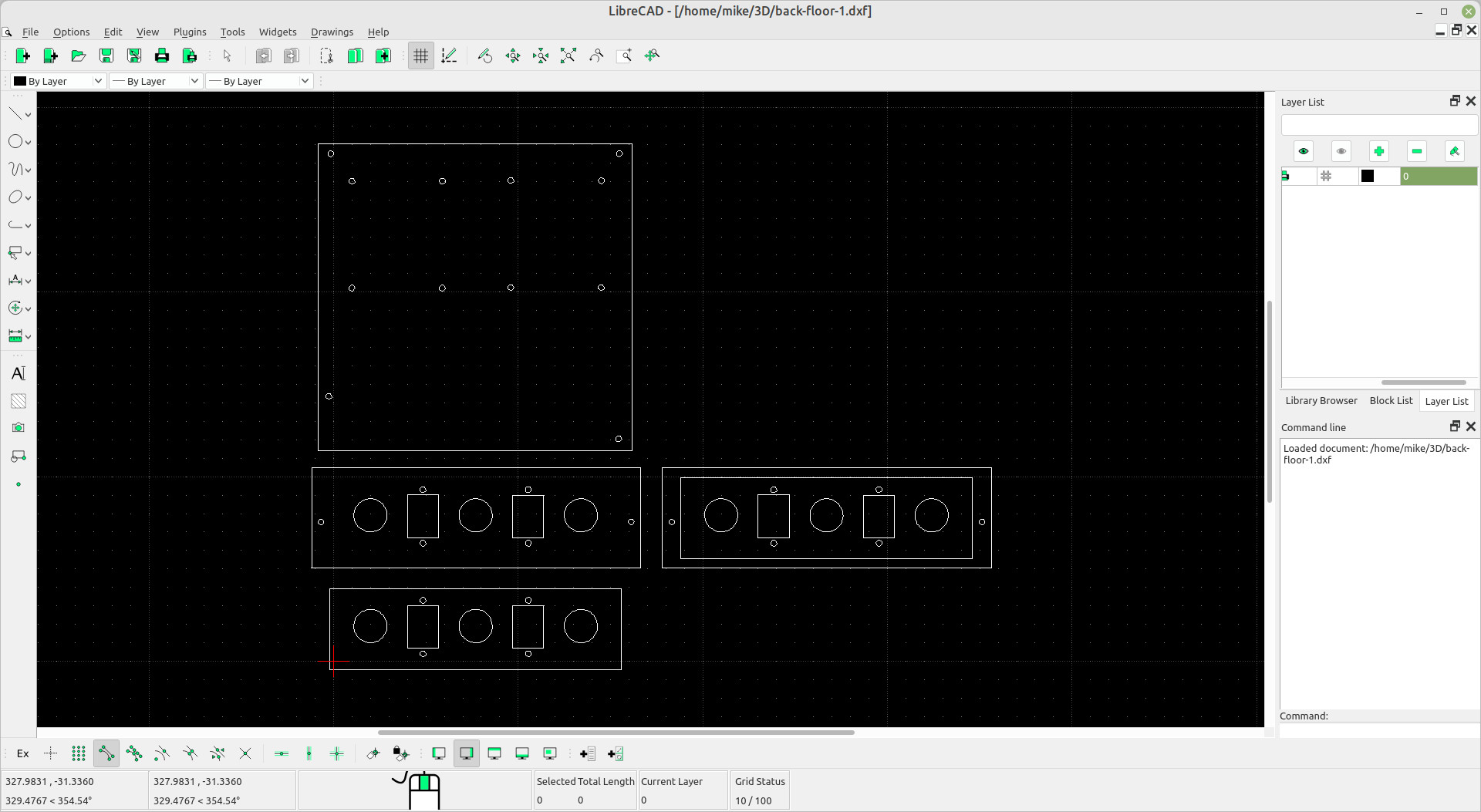
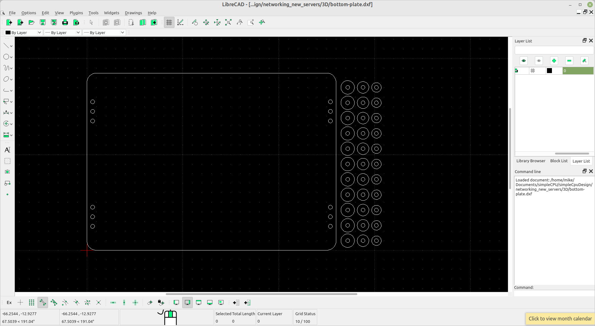
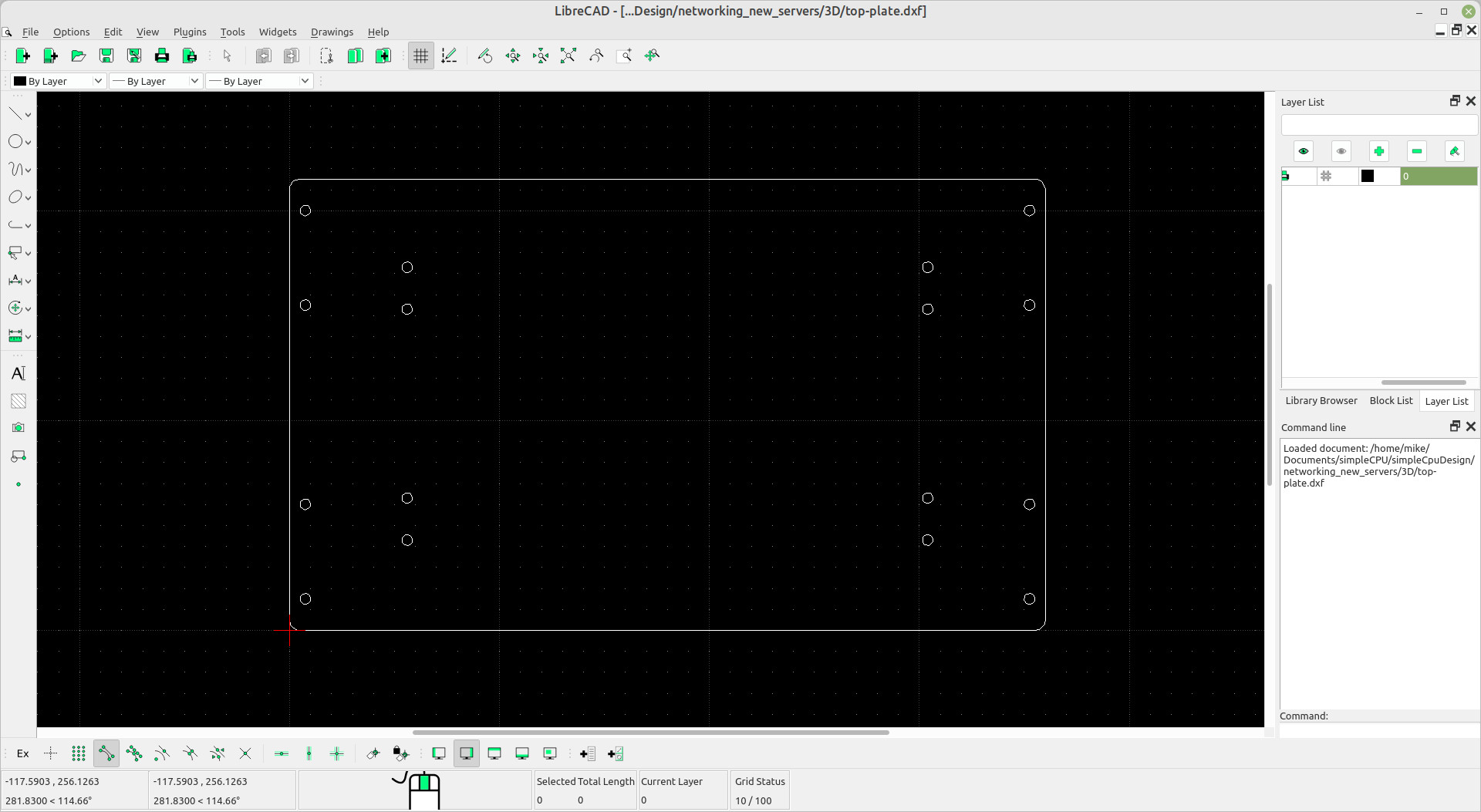
Figure 13 : laser cutter DXF files


Figure 14 : 3D printer STL files

Figure 15 : GPS receiver
Decided to try a cheaper (£7) GPS receiver, a Glonass Ublox7, i think. The Amazon listing name was a bit confusing. However, after a bit of Googling it did seem to have been interfaced with a Pi. So the normal setup for a GPS:
sudo apt update
sudo apt install gpsd gpsd-clients chrony
Then setup the driver by editing /etc/default/gpsd to:
START_DAEMON="true"
USBAUTO="true"
DEVICES="/dev/ttyACM0"
GPSD_OPTIONS="-n"
A reboot then test if things are working using:
sudo systemctl is-active gpsd
sudo systemctl is-active chronyd
If all good can used the commands: gpsmon or cgps to view live GPS data. That all seemed to work ok, but i need an NTP server, i confess not sure if chrony and ntp play nicely, but installed it anyway :)
sudo apt update
sudo apt install ntp

sudo apt purge fake-hwclock
sudo systemctl disable fake-hwclock
Then setup the driver by editing /etc/ntp.conf to:
#GPS
server 127.127.28.0
fudge 127.127.28.0 time1 0.0 refid GPS

#RTC
server 127.127.1.0
fudge 127.127.1.0 stratum 12

broadcast 192.168.1.255
You should be able to use ntpq -p to check time sync i.e. see GPS as one of the listed sources, as shown in figure 15. So we can see that both the RTC and GPS sources have been identified, but have been rejected as time sources indicated by the leading "x", an offset of 30ms and a jitter of 2ms. Note, it did settle down after about 30 minutes to an offset of 6ms and a jitter of 5ms, at which time both "x" were removed, sooo i am assuming all is good.
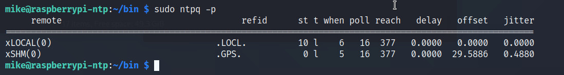
Figure 16 : ntp time sources
Confess, not sure why these are not being used as a clock source initially. I did also have issues with the ntp server syncing to these time sources as the GPS receiver struggles to lock on to the required number of satellites. Asking around the general opinion was it is the UV filters on the windows in the department, this also messes with the phone signals :(. Sooo bodge 3, everything can be fixed in software :). I have a python program that extracts the time data from the available GPS data stream and uses this to set the system time. The python code:
import gps
import threading
import queue
import time

def gps_worker(q):
    session = gps.gps(mode=gps.WATCH_ENABLE)
    while True:
        report = session.next()
        if report['class'] == 'TPV' and 'time' in report:
            q.put(report['time'])
            break

q = queue.Queue()
t = threading.Thread(target=gps_worker, args=(q,))
t.start()

try:
    gps_time = q.get(timeout=10)  # Wait up to 10 seconds
    print("GPS Time:", gps_time)
except queue.Empty:
    print("Timeout: No GPS time received.")
If the GPS is working ok this will print an output like that shown in figure 16

Figure 17 : GPS time
We can then use this in a Bash script to update the OS system time using the date command, as shown below. This is called via a cron job @reboot and then every 30 minutes. This approach is never going to be as accurate as a true Stratum 1 time server, but for the purposes of teaching i don't need to be be, seconds level of accuracy is fine and i found this approach works more reliably when you have very poor GPS signal strengths.
#!/bin/sh
/usr/bin/python3 /home/mike/bin/read-gps-timeout.py > /home/mike/bin/timeDate

if test $? -eq 0
then
  timeDate=`cat /home/mike/bin/timeDate | tr -s ' ' | cut -d' ' -f3`
  echo "Setting date to : $timeDate"
  sudo date -s "$timeDate"
else
  echo "Error: can not read GPS"
fi
The final piece of the ntp server is an LED clock display shown in figure 18, useful for telling the time and also for identifying when the ntp server stops working :). Again got this from Amazon, i never learn :), the only issue was no documentation, no support. I identified it uses a ht16k33 drive IC, so it has an I2C interface and with a bit of trial and error got it working. Note, the STL for the case can be downloaded here: (Link).


Figure 18 : LED clock display (top), 3D printed case (bottom)
Software needed:
LED DISPLAY
-----------
sudo apt-get install python3-venv python3-full
python3 -m venv clock
cd clock
source bin/actvate
pip3 install ht16k33-python
pip3 install adafruit-blinka
pip3 install RPi.GPIO
This code reads the OS system time and displays HH:MM on the LED display below. Confess Copilot AI generated, however, this is the first python program i had to manually debug i.e. normally Copilot is very good at writing python, but there was something about the HT16K33 lib it did not like and just like me Copilot could not be told it was wrong :). I decided to only update every 30 seconds, rather than every second. Updating every second felt like a large overhead for the Pi, but i guess there are 4 cores and it doesn't really have a lot to do, but for the moment sticking with the slight lag in update.
from ht16k33 import HT16K33Segment
import busio
import board
from datetime import datetime
import time

# Initialize I2C and display
i2c = busio.I2C(board.SCL, board.SDA)
while not i2c.try_lock():
    pass

display = HT16K33Segment(i2c)
display.set_brightness(5)
display.set_colon(True)  # Show colon between hour and minute

# Function to update time
def update_time():
    now = datetime.now()
    hour = now.hour
    minute = now.minute

    # Format time as HHMM
    digits = f"{hour:02d}{minute:02d}"

    for i, char in enumerate(digits):
        display.set_number(int(char), i)

    display.update()

# Loop to refresh every second
try:
    while True:
        update_time()
        time.sleep(30)
except KeyboardInterrupt:
    display.set_colon(False)
    print("Stopped.")
Pip was insistent that these libs needed to be used in a virtual environment, so thats what i did. The python code is auto stated on boot using a cron job, a bash script that activates this environment and run the code:
#!/usr/bin/bash
source /home/mike/clock/bin/activate
python3 /home/mike/clock/display-time.py &
In many respects no change here just Pi-hole, so this should have been the same as the previous DNS server (Link), however, the people at Pi-hole decided to "improve" their software :(. When i was a lad a config file was a file that an application read when it was started, so it could load parameters. Thats how the custom.list in pi-hole used to work, a plain text file that containing your local name to IP address mappings (described in previous DNS server setup). Now it seems that this is auto generated by pi-hole from another sources :(. Confess, ive forgot how i got this working, i think i used the following script to again generate the name to number mappings:
#!/bin/bash

echo -n > custom.list

for i in $(seq -w 1 99)
do
  #echo $i
  for j in 1 2 3
  do
    echo "  \"192.168.$i.$j pi-$j.desk$i.lan\"," >> custom.list
    #echo "192.168.$i.$j pi-$j.desk$i.lan" >> custom.list
  done
done
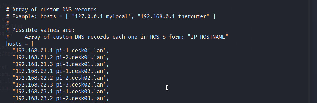
Figure 19 : pihole.toml
Then following the instructions in the auto generated custom.list file i copied these into the appropriate section of the file /etc/pihole/pihole.toml, as shown in figure 19, another auto generated file. Then looking back at my bash_history file it looks like i ran these commands:
sudo pihole reloadlists
sudo pihole restartdns
Could go back and test this, but as it works not keen to break it :). Setting up the TTL value and return routes are the same as last time (link above).
This build was identical to the original (Link) :). The plan was to also install SAMBA, but i forgot, so this required me to download the required deb files and manually install, soooo, on the Pi:
sudo apt-get install samba --print-uris -y | tee files.txt
Copy files.txt to a PC with internet access and run the script:
#!/bin/bash

FILE="files.txt"
DOWNLOAD_DIR="samba-packages"

mkdir -p "$DOWNLOAD_DIR"

grep -oE "'http[^']+'" "$FILE" | tr -d "'" | while read -r url
do
  echo "Downloading: $url"
  wget -P "$DOWNLOAD_DIR" "$url"
done
Tar up this DIR and copy to the Pi, untar and run:
sudo dpkg -i /home/pi/samba-packages/*.deb
Did have to manually go back and download and install : python3-h11_0.14.0-1.1_all.deb, but we seem to have a working install, confess have not tested / configure it, but it all started fine, so it must work :).
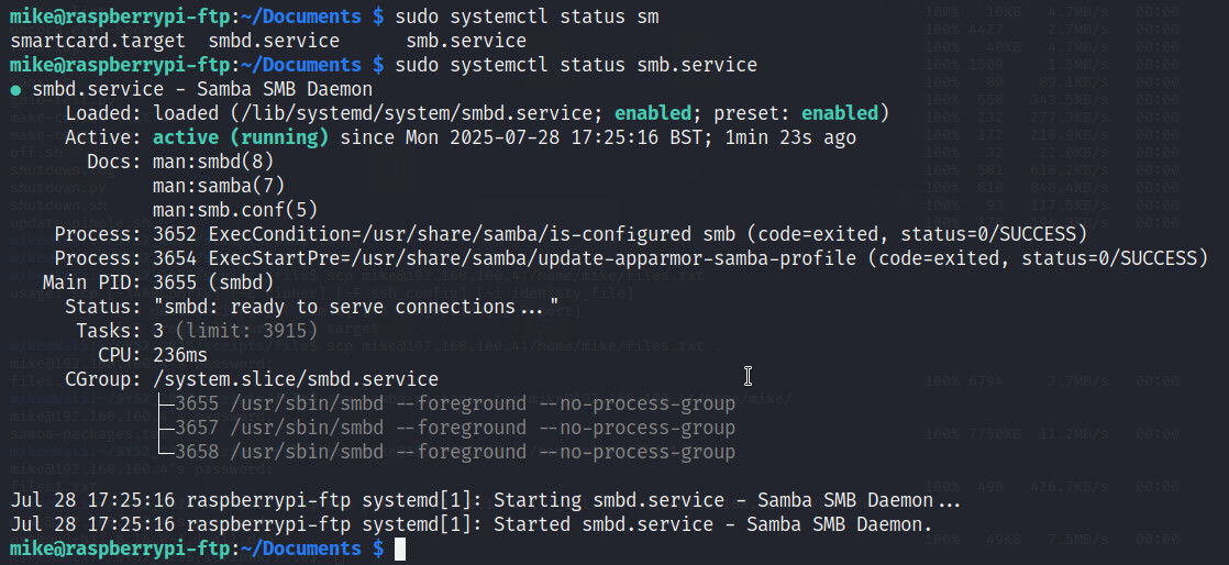
Figure 20 : smbd service
# See /usr/share/postfix/main.cf.dist for a commented, more complete version

smtpd_banner = $myhostname ESMTP $mail_name (Raspbian)
biff = no

# appending .domain is the MUA's job.
append_dot_mydomain = no

readme_directory = no

# See http://www.postfix.org/COMPATIBILITY_README.html -- default to 2 on
# fresh installs.
compatibility_level = 2

# TLS parameters
smtpd_tls_cert_file=/etc/ssl/certs/ssl-cert-snakeoil.pem
smtpd_tls_key_file=/etc/ssl/private/ssl-cert-snakeoil.key

smtpd_use_tls=no

smtpd_tls_session_cache_database = btree:${data_directory}/smtpd_scache
smtp_tls_session_cache_database = btree:${data_directory}/smtp_scache

smtpd_relay_restrictions = permit_mynetworks permit_sasl_authenticated defer_unauth_destination

myhostname = raspberrypi-mail.lan
mydomain = raspberrypi-mail.server
myorigin = $mydomain
alias_maps = hash:/etc/aliases
alias_database = hash:/etc/aliases
mydestination = $mydomain, localhost.$mydomain, localhost
relayhost =
mailbox_size_limit = 0
recipient_delimiter = +

inet_interfaces = all
inet_protocols = ipv4

home_mailbox = Maildir/
mailbox_command =
The main.cf file for the base node Pis system are (some small variations):
# See /usr/share/postfix/main.cf.dist for a commented, more complete version
smtpd_banner = $myhostname ESMTP $mail_name (Raspbian)
biff = no
# appending .domain is the MUA's job.
append_dot_mydomain = no
readme_directory = no
compatibility_level = 2

# TLS parameters
smtpd_tls_cert_file=/etc/ssl/certs/ssl-cert-snakeoil.pem
smtpd_tls_key_file=/etc/ssl/private/ssl-cert-snakeoil.key
smtpd_use_tls=yes
smtpd_tls_session_cache_database = btree:${data_directory}/smtpd_scache
smtp_tls_session_cache_database = btree:${data_directory}/smtp_scache
smtpd_relay_restrictions = permit_mynetworks permit_sasl_authenticated defer_unauth_destination

myhostname = pi-3.desk07.lan
mydomain = pi-3.mail.server
myorigin = $mydomain
alias_maps = hash:/etc/aliases
alias_database = hash:/etc/aliases
mydestination = $mydomain, localhost.$mydomain, localhost
relayhost = 192.168.100.2:25
mynetworks = 127.0.0.0/8, 192.168.0.0/16
mailbox_size_limit = 0
recipient_delimiter = +
inet_interfaces = all
#inet_protocols = all
inet_protocols = ipv4

home_mailbox = Maildir/
mailbox_command =
New for this year. This server was inspired by this video (Link). The thought here was that i could use Docker to create a virtual network of networks and hosts that could still be accessed across the lab's network. The first thing to do was to create some Docker networks:
sudo docker network create --subnet 10.0.0.0/24 net-1
sudo docker network create --subnet 10.0.1.0/24 net-2
Next we need to create a new docker image based on Alpine with SSH and all the required networking tools. The Dockerfile to do this is:
# To create new image
# docker build -t alpine-ssh .
# docker run -itd --name host-1 alpine-ssh
# docker exec -it host-1 passwd pi

FROM alpine:latest

# Install required packages
RUN apk update && \
    apk add --no-cache openrc && \
    apk add --no-cache nmap && \
    apk add --no-cache iproute2 && \
    apk add --no-cache openssh && \
    adduser -D pi && \
    echo "pi:12345" | chpasswd && \
    rc-update add sshd && \
    mkdir -p /run/openrc && \
    touch /run/openrc/softlevel

# Note, the empty file softlevel is needed to ensure sshd runs

# Enable IP forwarding
RUN echo "net.ipv4.ip_forward=1" >> /etc/sysctl.conf && \
    echo "net.ipv6.conf.all.forwarding=1" >> /etc/sysctl.conf

# Configure SSH
RUN sed -i 's/^#PermitRootLogin.*/PermitRootLogin no/' /etc/ssh/sshd_config && \
    sed -i 's/^#PasswordAuthentication.*/PasswordAuthentication yes/' /etc/ssh/sshd_config

# Expose SSH port
EXPOSE 22

# Start services and enable IP forwarding on container start
#CMD sh -c "sysctl -p && rc-service sshd start"
This creates the alpine-ssh image that can then be used to create a container for our new network host. To start this virtual machine we can use this script:
echo "Create HOST-1"
sudo docker run -itd --name host-1 --network net-1 --ip 10.0.0.5 --privileged alpine-ssh sh
sudo docker network connect --ip 10.0.1.20 net-2 host-1
sudo docker exec host-1 ip route del default
sudo docker exec host-1 ip route add 192.168.0.0/16 via 10.0.0.1
sudo docker exec host-1 rc-service sshd start
This process was replicated a number times to create multiple networks and hosts i.e. each host was connected to multiple networks to create a tree of hosts and networks to explore. These networks appear as a number of bridge interfaces on the Pi i.e. virtual switches. To prevent external hosts from seeing these we need some iptables rules to restrict access:
echo "Block external access"
sudo iptables -I INPUT -d 10.0.1.0/24 -j DROP
sudo iptables -I INPUT -d 10.0.2.0/24 -j DROP
sleep 1

echo "Add forwarding rules"
interface=`ip a | grep br- | grep 10.0.0.255 | tr -s ' ' | cut -d' ' -f8`
sudo iptables -I FORWARD -i $interface -o eth0 -j ACCEPT
sudo iptables -I FORWARD -i eth0 -o $interface -j ACCEPT
In addition to these the FORWARD default is set to DROP, and only the 10.0.0.0 network is allowed to forward traffic to/from the physical NIC eth0. Note, the file /etc/sysctl.conf also needs to be updated with net.ipv4.ip_forward = 1. This all seems to work quite nicely. To connect to Host-1 on IP address 10.0.0.5 a user needs to add a routing rule their Pi:
sudo ip route add 10.0.0.0/24 via 192.168.100.7
They can then SSH into this Docker container as normal using the normal user name and password:
ssh pi@10.0.0.5
Then a user can explore / see what host is connected to what using the ping and nmap commands to explore this new virtual network.
New for this year. This server was inspired by the promise of more e-waste, some old VOIP phones, and the fact that with three thin-client boxes, so i had six Pis available, so i felt i needed to do something with the final Pi :). To start with i installed an IRC (Internet Relay Chat) server. This is a text based communication protocol designed for real-time messaging over the internet. It’s one of the oldest chat systems still in use today. Soooo, to install this server:
sudo apt-get install ircd-hybrid
Then to configure this server you need to edit the file /etc/ircd-hybrid/ircd.conf, most is default, below are the changes, Bob's chat room is open to all:
serverinfo {
	name = "raspberrypi-irc.lan";
	description = "Bob's IRC server";

	network_name = "lan";
	network_description = "This is Bob's Network";

	hub = no;
	default_max_clients = 100;
	max_nick_length = 15;
	max_topic_length = 300;

	rsa_private_key_file = "/etc/ircd-hybrid/key/ircd.key";
	tls_certificate_file = "/etc/ircd-hybrid/key/ircd.pem";
	tls_dh_param_file = "/etc/ircd-hybrid/key/dhparam.pem";
};

operator {
	name = "bob";
	user = "*@*";
	password = "$y$j9T$fcxWcYEcbE5qxC57YIUTd1$B7b4hYZCvrRRMFIQgnt83Ani1HHai5RZ3P0UvbUfBk0";
	encrypted = yes;
};
To access this server i installed the IRC client HexChat, to install:
sudo apt-get install hexchat
Voice over IP i have no idea, but Asterisk seems to be the default way of doing things, so i installed a Docker container that seemed to be ok:
docker run -d \
  --name freepbx-app \
  -p 80:80 \
  -p 5060:5060/udp \
  -p 5160:5160/udp \
  -p 18000-18100:18000-18100/udp \
  -v /home/mike/Docker/asterisk17/certs:/certs \
  -v /home/mike/Docker/asterisk17/data:/data \
  -v /home/mike/Docker/asterisk17/logs:/var/log \
  -v /home/mike/Docker/asterisk17/data/www:/var/www/html \
  -v /home/mike/Docker/asterisk17/db:/var/lib/mysql \
  --env DB_EMBEDDED=TRUE \
  --env RTP_START=18000 \
  --env RTP_FINISH=18100 \
  --env VIRTUAL_HOST=asterisk.local \
  --env VIRTUAL_PORT=80 \
  --cap-add=NET_ADMIN \
  --privileged \
  epandi/asterisk-freepbx-arm:17.15-latest
Have not tested yet. Finally, just in case that did not work installed an alternative, Mumble:
sudo apt install mumble-server -y

sudo dpkg-reconfigure mumble-server
Autostart: Yes
High Priority: Yes
Set a SuperUser password (admin access)
I believe you can also setup stuff in /etc/mumble-server.ini
welcometext="Welcome to Bob's Mumble server"
serverpassword=password
users=20
port=64738
To restart:
sudo systemctl restart mumble-server
Again, have not tested yet, but hope to get some VOIP phones this term.
WORK IN PROGRESS

This work is licensed under a Creative Commons Attribution-NonCommercial-NoDerivatives 4.0 International License.
Contact email: mike@simplecpudesign.com