The first version of the simpleCPU (Link) demonstrated how a simple processor and a general purpose input/output peripheral device could be used to implement the classic "Hello World" programming task. However, the solution shown was written using a cut-and-paste style of coding, therefore, was a little hard to read. To improve upon this i decided to rewrite this example and give it a little more structured. This serial IO (SIO) example is implemented using software emulation i.e. bit-banging:
"slang for various techniques for data transmission in which software is used to generate and process signals instead of dedicated hardware"
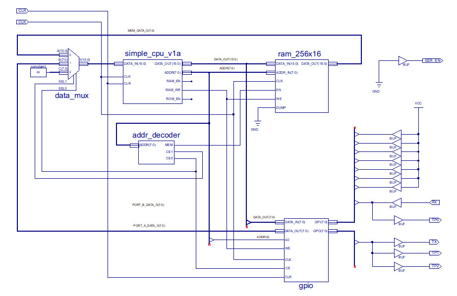
This bit-banged implementation of the "Hello World" program will transmit serial data at 300 bps using GPIO to implement the serial port. The system used to implement this is shown in figure 1 (top level) and 2 (GPIO). Note, the GPIO port is memory mapped to address OxFC, in this design i'm only using the output port on the GPIO i.e. TX only, need to write the RX code at some point :). The complete ISE project can be downloaded here: (Link)
Figure 1 : top level system schematic
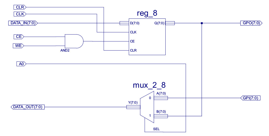
Figure 2 : general purpose input / output port (GPIO)
Therefore, to "print" this message its just the simple task of controlling the output port, setting the output pin to a logic 0 or logic 1 at the correct times, to produce the serial packet format shown in figure 3 i.e. emulate the signals that would normally be produced by a Universal Asynchronous Receiver Transmitter (UART) unit, a hardware implemented serial port.
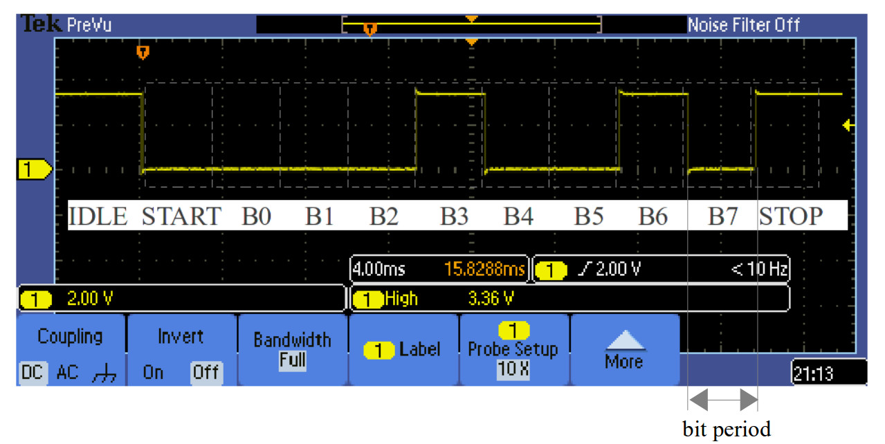
Figure 3 : serial data packet
However, before we look at how we will transmit the "Hello World" message we need to decide how these characters are represented i.e. what numerical value is assigned to each character. To do this we will use the ASCII representation shown in figure 4 (Link). Therefore, looking back to figure 3 we can see that the data transmitted in this serial data packet is the letter "H" i.e. the value 0x48.
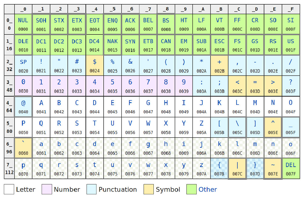
Figure 4 : ASCII
The pseudo code used to implement a serial transmitter is shown below:
    set serial line low
    wait 3.3ms
    for i in range 0 to 7
    	set serial line to DATA(i)
    	wait 3.3ms
    set serial line high
    wait 3.3ms
One of the functions identified in this pseudo code description is a 3.3 ms time delay i.e. the bit period (1/300). This will be implemented using the software time delay function shown in figure 5. Knowing the processor's clock speed and the number of clock cycles needed per instruction (CPI), we can implement a FOR loop to cause the processor to execute this number of instructions and therefore the required time delay.
    delay:
        move    XX           # save outer loop count
        store   CNT

    innerLoop:
        move   0x00         # load inner count
        sub    0x01         # dec inner delay loop
        jumpz  outerLoop    # exit if 0
        jump   innerLoop    # repeat

    outerLoop:
        load   CNT          # load outer loop counter
        sub    0x01         # dec outer loop count
        store  CNT
        jumpnz innerLoop    # repeat if not zero
        jump   exit         # exit

    CNT:
        .data 0             # outer loop count variable
Figure 5 : time delay function
The simpleCPU runs at 10MHz and each instruction takes 3 clock cycles to execute, therefore, the number of instructions that need to be executed is:
Instruction count = (3.3x10^-3) / (1/10x10^6)x3 = 11000
Rather than having a block of 11000 "dummy" instructions e.g. move 0 x 11000 times, which would be very inefficient in terms of code density, and would also not fit into the simpleCPU's 256 memory, the software delay function uses two nested FOR loops to burn through the required number of instructions:
    Instructions executed   = 2 + (1 + (3x256)+4) x CNT
			                = 2 + 773 x CNT = 11 x 10^3

    CNT = (11 x 10^3) / 773 = 14.2 = 14 to 15-ish :)
Would of liked a non-fractional result :(, but if needed we can play around with the inner loop counter to try and minimise this error. However, as the bit period delay is relative to each data packet i.e. reset on the next start bit, the accumulated error is not so significant, so this should be fine. As this functionality is needed three times a macro was created, as shown in figure 6.
    define(delay, `
        move   $1
        store $2

    delayLoop$3:
        move 0
    innerLoop$3:
        sub 1
        jumpz outerLoop$3
        jump innerLoop$3

    outerLoop$3:
        load $2
        sub 1
        store $2
        jumpnz delayLoop$3'
    )
Figure 6 : time delay function
This macro is called within the program as:
delay(15, COUNT, 1)
The first parameter is the outer loop count value, second the address of the variable used to store it (symbolic name COUNT in this example) and lastly the delay ID, used to ensure unique label names, as this macro is used multiple times within the program. To confirm that this macro will produce the required time delay i wrote the simple test program shown in figure 7. This program sets/clears the output port every 3.3ms, which can then be displayed / measured on a scope. The resulting 150Hz square wave is shown in figure 8, which looks close enough to the 3.3ms delay needed for the purposes of this program.
    start:
        move    0               # clear port
        store   0xFC
        delay( 15, COUNT, 1 )   # delay 1

        move    0xFF            # set port
        store   0xFC
        delay( 15, COUNT, 2 )   # delay 2

        jump start
    COUNT:                      # count
        .data 0                 # variable
Figure 7 : time delay test code
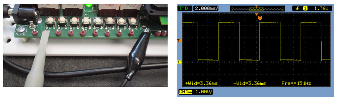
Figure 8 : time delay test
Data is transmitted on the serial line one bit at a time, starting at the least significant bit (LSB) position. Therefore, the software needs to test the state of each bit i.e. is it a logical 0 or 1. One possible solution to this problem is to always test the same bit position, but then shift the data bits within the accumulator, as shown below:
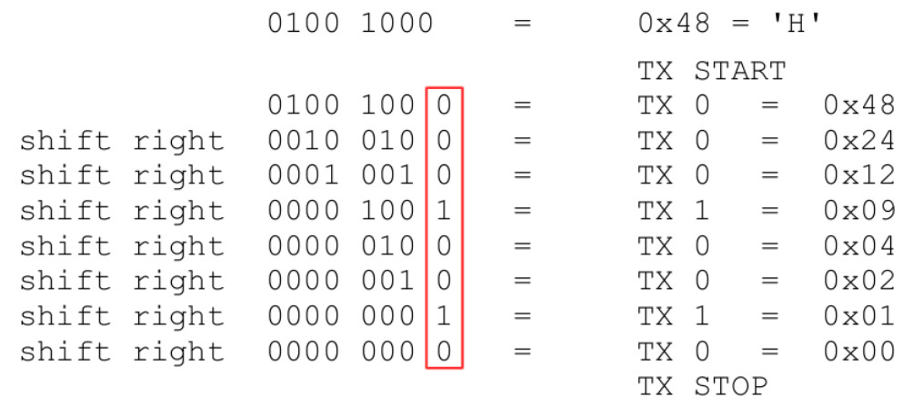
Figure 8 : shift function
Here the data value is shifted right one bit position each time, inserting a logic 0 into the MSB position. The processor transmitting the LSB on the TX line. If you look at the resultant value (on the right) you can observe that this results in the data value being divided by 2. An easy but some what inefficient method of performing multiplication or division is through repeated addition or subtraction. Consider the pseudo code shown below:
	DIVIDEND = 100
	DIVISOR = 3
	QUOTIENT = 0

	while DIVIDEND > 0
		DIVIDEND = DIVIDEND –  DIVISOR
		if  DIVIDEND > 0
			QUOTIENT = QUOTIENT +1
Therefore, one method of shifting the data value to the right is to repeatedly subtract 2 from the ASCII character, counting the number of times this can be performed without producing a negative result. The final count value being the original data divided by 2. One possible implementation of this pseudo code is shown in figure 9.
    div:
        move   0x00     # zero divide count
        store  CNT      #

    loop:
        load   CHAR     # load char, sub 2
        sub    0x02
        store  CHAR     # save result
        and    0x80     # test if neg
        jumpnz exit     # yes exit

        load   CNT      # no increment divide
        add    0x01
        store  CNT
        jumpu  loop

    exit:
        load   CNT      # update result
        store  CHAR
        jumpu  next
Figure 9 : divide by 2 test code
Again to improve readability this code was implemented as a macro called "shiftRight". This macro should be passed the memory address of the variable to be shifted and the memory locations of any intermediate variables or labels used.
    define( shiftRight, `
        move 0
        store $1
    div_loop:
        load $2
        sub 2
        store $2
        and 0x80
        jumpnz div_exit
        load $1
        add 1
        store $1
        jump div_loop
    div_exit:
        load $1
        store $2'
    )
This is called within the program as:
shiftRight( CNT, CHAR )
The first parameter is the address of the temporary variable used to store intermediate values produced during the division, in this example symbolic name CNT. The second parameter is the address of the character being processed, in this example symbolic name CHAR. The data stored at this address will be overwritten with the final result. This macro does not produce unique label names, therefore, it is assumed it is only called once within a program.
The next problem we need to consider is how we store and access the characters used to represent the string "Hello World". The bit-banged serial port can be described by the pseudo code shown below:
	for I in range 0 to 10
		transmit DATA(I)

	DATA: H,E,L,L,O, ,W,O,R,L,D,\0
Here we assume that the data string is stored in sequential memory locations i.e. an array, and the transmit program iterates through this array, transmitting one character after the next. However, the issue with this implementation is that the simpleCPU's LOAD instruction only supports the absolute addressing mode i.e. the address read is hard-coded and can not be changed at run time. Therefore, at first glance it seems that this FOR loop based solution will be impossible. However, one dodgy solution to this problem is to use self-modifying code. Using this technique the address field of the LOAD instruction is overwritten with the address of the next character each time the transmit function is performed. This is discussed in detail in the simpleCPU_v1a documentation : (Link).
Note, to state the obvious self-modifying code is not a recommended programming technique. However, it was used extensively in old computers as it helped reduce hardware costs and improved memory usage. To remove the need for this programming technique modern processors support additional addressing modes e.g. register-indirect, memory-indirect and indexed, which are supported in later versions of the simpleCPU processor e.g. simpleCPU_v1d.
Using the previously defined macros and self modifying code to allow us to overwrite a LOAD instruction with a new absolute address, we can now implement the program functions required to print “Hello World” on the screen. One possible pseudo code implement is shown in figure 10. Note, the end of the string is indicated using a NUL character i.e. “\0”, the value 0.
	PNTR = 0
	loop:
		CHAR = DATA[PNTR]
		if CHAR = 0
			exit

		set serial line LOW
		wait for 3.3ms

		for I in range 0 to 7:
			set serial line to CHAR[I]
			wait for 3.3ms

		set serial line HIGH
		wait for 3.3ms

		PNTR = PNTR + 1

	DATA : H,E,L,L,O, ,W,O,R,L,D,0
Figure 10 : print message pseudo code
The resulting assembly code is shown in figure 11.
    # INTERFACE - GPIO: ADDR 0xFC
    # Q7 to Q1    /* NU */
    # Q0;         /* TX */

    start:
	    move   0x01      		# set default state = 1
	    store  GPIO

	    move   0x00      		# zero char count
	    store  charCount

    txLoop:
	    load   charCount         # load char count
	    add    message        	# add base offset
	    store  txChar    		# overwrite load address

    txChar:
	    load   txChar      		# read char
	    jumpz  exit        		# finish if char=NULL

	    store  txBuff        	# buffer char
	    move   0x08      		# set bit count
	    store  txBitCnt

	    load   charCount         # load char count
	    add    0x01      		# inc
	    store  charCount

	    move   0x00      		# start bit = 0
	    store  GPIO

	    delay(15, delayCnt, 1)

    txCharLoop:
	    load   txBuff        	# load buffer char
	    and    0x01      		# mask bit
	    store  GPIO      		# update port

	    delay(15, delayCnt, 2)

	    load   txBitCnt          # load bit count
	    sub    0x01      		 # dec
	    store  txBitCnt
	    jumpz  stopBit           # finished, TX stop bit

	    shiftRight(tmp, txBuff)

	    jumpu txCharLoop         # repeat until all bits TX

    stopBit:
	    move   0x01      		# stop bit = 1
	    store  GPIO

	    delay(15, delayCnt, 3)

	    jump   txLoop        	# repeat

    exit:
	    jump   exit        		# trap

    # VARIABLES

    charCount:
	    .data 0
    txBuff:
	    .data 0
    txBitCnt:
	    .data 0
    delayCnt:
	    .data 0
    tmp:
	    .data 0

    # DATA CHARACTERS TO DISPLAY

    message:
	    .data   72        # H    - 01001000
	    .data   69        # E    - 01000101
	    .data   76        # L    - 01001100
	    .data   76        # L    - 01001100
	    .data   79        # O    - 01001111
	    .data   32        # SP   - 00100000
	    .data   87        # W    - 01010111
	    .data   79        # O    - 01001111
	    .data   82        # R    - 01010010
	    .data   76        # L    - 01001100
	    .data   68        # D    - 01000100
	    .data   10        # CR   - 00001010
	    .data   13        # LF   - 00001101
	    .data   0         # NUL  - 00000000
Figure 11 : print message assembly code : helloWorld.asm
To produce the required memory.vhd configuration file for this system run the following script:
m4 simpleCPUv1a.m4 helloWorld.asm > code.asm
python simpleCPUv1a_as.py -i code -o code
python simpleCPUv1a_ld.py -i code
The assembler is available here: (Link), make sure you get the new version :). To test your solution open the simulation testbench computer_TB contained within the project zip file (link at top of page). Run this simulation for 500 ms, if all is working correctly you should see the waveform shown in figure 12. Serial data is transmitted on the TX pin (mirrored on TP1 and TP2, these are connected to an LED and external test point for the scope). This serial data is decoded within the testbench and the transmitted character displayed.
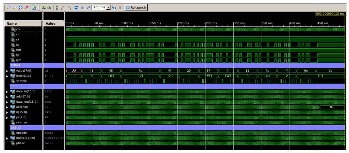
Figure 12 : testbench waveform
This design can then be downloaded onto the FPGA, the serial TX and RX pins are buffered through the classic MAX232 line driver (Link). This is connected to a DE-9 connector and a NULL modem serial cable (Link) is used to connect the FGPA to the PC. On the PC end i'm using an USB-to-Serial adapter. Gone are the days when PC had serial ports :). Note, some motherboards still do have serial ports, however, these tend not to be connected to the outside world i.e. IO headers only. To see the transmitted message i use Putty (Link) on Windows boxes and Screen on Linux. The Putty configuration is shown in figure 13. The result message in figure 14. Note, i like this demo as you can feel / see the 300bps delay as the characters are slowly printed on the terminal :).
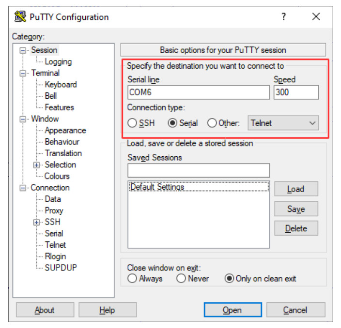
Figure 13 : Putty config
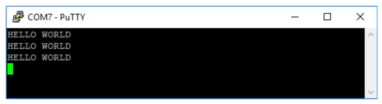
Figure 14 : Hello World message

This work is licensed under a Creative Commons Attribution-NonCommercial-NoDerivatives 4.0 International License.
Contact email: mike@simplecpudesign.com