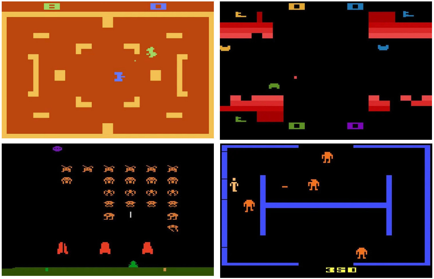
From the beginning of this journey into processor design the long term aim of this project was to build an Atari 2600 style games console i.e. design a processor and its associated peripheral devices that were capable of executing simple game code: Pong, Combat, Space Invader etc, as shown in figure 1. The second requirement was that this system must be affordable i.e. cheap FGPAs, that could be implemented in FPGAs with limited hardware resources, both in terms of memory and logic. Note, i did considered using boards with an external memory, but, these tend to bump up the cost quite a bit when compared to a single IC solution. Linked into this second requirement is the hardware used to implement the display interface e.g. display port, HDMI, DVI or VGA. Modern high speed display interfaces require a lot of hardware and special connectors, which increases costs, so to keep things cheap and cheerful going to stick with VGA (Link). Note, this design choice may seem to limit the range of compatible displays, but VGA-to-HDMI adapters are only £10 :). Finally, the third requirement was the capability to implement a game's functionality using some sort of high level "language", minimising or removing the need for assembly language programming. This high level software implementation is not going to be your traditional C type language. Writing a compiler is just tooo much fun. Therefore, i decided to go for a simple M4 macro based approach, abstracting away from assembler through the use of a set of general purpose macros and subroutines. A video of the first prototype "Space Invaders" demo in action is available here: (Link).
Note, will probably come back to a C compiler another time, but this feels like its going to be a significant piece of work. There is never enough time :).
Figure 1 : Atari 2600 type games
Unlike the previous SimpleCPU Pong game (Link that used serial-terminal commands to implement it's display, this games console will need a video controller, owing to the serial-ports communications bottleneck and resulting low frame rate. In the Pong game these limitations were not too much of an issue owing to the low number of graphical elements moving on the screen. Therefore, by only updating those pixels that had changed, a reasonably "fast" redraw rate could be achieved. In games such as Space Invaders that contain multiple sprites (graphical elements), there would be insufficient serial-port bandwidth, resulting in a verrrry slow frame rate.
The terms Video Display Controller (VDC), Video Interface Controller (VIC), or Graphical Processing Unit (GPU) all have slightly different meanings and offer differing levels of functionality and processing power. To keep things simple (as i'm designing this hardware from scratch), i'm going for a VDC style of display interface i.e. most of the graphical processing will be performed on the CPU, with the VDC only supporting basic text and graphics functions. For more information on these devices refer to: (Link), (Link), (Link).
When starting work on the video controller the first design consideration is what hardware resources are available within the FPGA, in particular how much memory is available to implement the video memory's frame buffer and its associated graphics ROMs i.e. text fonts and graphical tiles (glyths). The frame buffer (Link) within the VDC is used to store the display's pixel data, so its size is dependent on the display's dimensions. If we assume that each pixel uses an RGB colour model (Link) and that R, G and B are represented using an 8bit value, we can calculate the display's frame buffer size for different screen resolutions:
800 x 600 pixels = 480,000 pixels
640 x 480 pixels = 307,200 pixels
320 x 240 pixels = 76,800 pixels
160 x 120 pixels = 19,200 pixels
80  x 60  pixels = 4,800 pixels

1 pixel = 8 + 8 + 8 = 24 bits = 16,777,216 colours

800 x 600 pixels = 480,000 x 24 = 11,520,000 bits = 1,440,000 bytes
640 x 480 pixels = 307,200 x 24 = 7,372,800 bits  = 921,600 bytes
320 x 240 pixels = 76,800  x 24 = 1,843,200 bits  = 230,400 bytes
160 x 120 pixels = 19,200  x 24 = 460,800 bits    = 57,600 bytes
80  x 60  pixels = 4,800   x 24 = 115,200 bits    = 14,400 bytes
As we can see the frame buffer needs significantly more memory than the processor that uses it, significantly more than a cheap FGPA will contain. In addition to the memory needed to store the displayed image, we would also need memory for text i.e. fonts (Link), and graphical elements used in the game i.e. tiles (Link) or sprites (Link).
Note, some standard VGA screen resolutions and sizes:
Name 	H (px) 	V (px) 	H:V 	H x V (Mpx)
QQVGA 	160 	120 	4:3 	0.019
HQVGA 	240 	160 	3:2 	0.038
QVGA 	320 	240 	4:3 	0.077
WQVGA 	384 	240 	16:10 	0.092
WQVGA 	360 	240 	3:2 	0.086
WQVGA 	400 	240 	5:3 	0.096
HVGA 	480 	320 	3:2 	0.154
VGA 	640 	480 	4:3 	0.307
WVGA 	768 	480 	16:10 	0.368
WVGA 	720 	480 	3:2 	0.345
WVGA 	800 	480 	5:3 	0.384
SVGA 	800 	600 	4:3 	0.480
To reduce memory requirements a number of different techniques can be used. In the early days of computing displays were limited to "text-mode" (Link). In such systems a monospace font is used, where each character has the same width and height, typically 8 x 8 pixels, as shown below:
 |     | |     |              |     | |     |              |     | |     |
 8 4 2 1 8 4 2 1              8 4 2 1 8 4 2 1              8 4 2 1 8 4 2 1
 . . # # . . . .  0x30        . . . . . . . .  0x00        # # # # # # . .  0xFC
 . # # # # . . .  0x6A        . . . . . . . .  0x00        . # # . . # # .  0x66
 # # . . # # . .  0xCC        . # # # # . . .  0x78        . # # . . # # .  0x66
 # # . . # # . .  0xCC        . . . . # # . .  0x0C        . # # # # # . .  0x7C
 # # # # # # . .  0xFC        . # # # # # . .  0x7C        . # # . . # # .  0x66
 # # . . # # . .  0xCC        # # . . # # . .  0xCC        . # # . . # # .  0x66
 # # . . # # . .  0xCC        . # # # . # # .  0x76        # # # # # # . .  0xFC
 . . . . . . . .  0x00        . . . . . . . .  0x00        . . . . . . . .  0x00
This bitmap indicates what pixels are illuminated to display each character (no colour information). Now, rather than remembering the state of each pixel the display is divided up into an array of character cells. Therefore, the VDC now only needs to remember what character is displayed in each cell, storing the font bitmaps in a ROM (font memory), and character cell data in RAM (text buffer), significantly reducing the total amount of RAM required, as shown in figure 2.
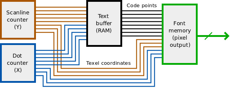
Figure 2 : text mode memory architecture (source Wikipedia)
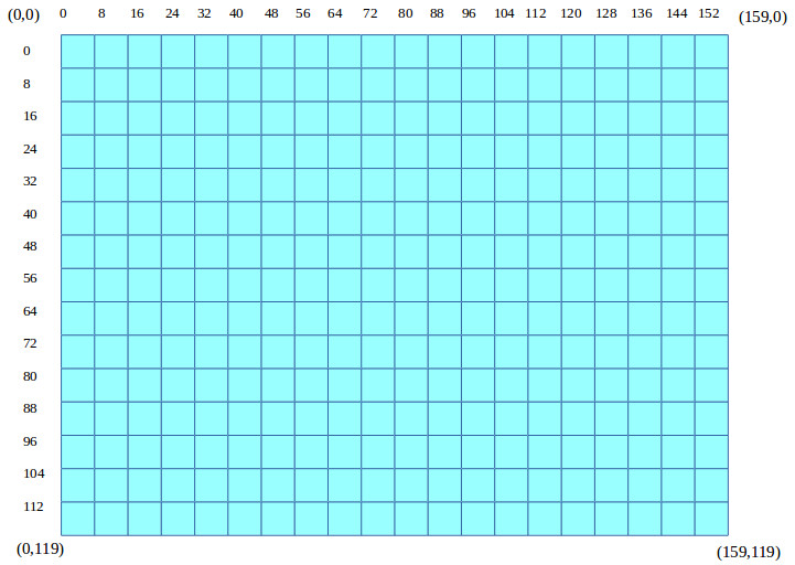
Figure 3 : character cell pixel positions
This is a very elegant method of reducing the VDC's RAM, but it does come at the cost of flexibility i.e. fixed position character cells, as shown in figure 3. We can use a similar approach to implement the VDC used in this games console and use 8 x 8 bitmaps to define fonts and graphic elements i.e. tiles. However, to allow smoother movement and animations we need the ability to place these tiles at any screen XY co-ordinate, rather than being limited to defined character cells, as used in the hardware shown in figure 2.
In addition to storing each character's bitmap we also need to store its colour i.e. its foreground and background colours. To do this we need to decide upon a colour palette: (Link). The more colours that need to be represented the more bits we will need. In the previous example we assumed 8 bits to represent the R, G and B values, but to reduce memory requirements this could be reduced to 2 bits :
1 pixel = 2 + 2 + 2 = 6 bits = 64 colours

800 x 600 pixels = 480,000 x 6 = 2,880,000 bits = 360,000 bytes
640 x 480 pixels = 307,200 x 6 = 1,843,200 bits = 230,400 bytes
320 x 240 pixels = 76,800  x 6 = 460,800 bits   = 57,600 bytes
160 x 120 pixels = 19,200  x 6 = 115,200 bits   = 14,400 bytes
80  x 60  pixels = 4,800   x 6 = 28,800 bits    = 3,600 bytes
These calculations are a little bit misleading, even though 6bits are used to represent each pixels value you would need to allocate an 8bit memory location, unless you want to do a lot of bit manipulation to unpack non-aligned values :(. Alternatively, we can ditch colour and go monochrome i.e. black and white (on or off). As we will be using a colour monitor, from an implementation point of view this display could be a black + 1 colour e.g. a shade of grey if we used the same value for R, G and B, or a shade of red, green or blue. As long as the VDC's RGB output only has to represent two states 0V and +V, we can represent these states with 1bit. This approach would reduce the RAM to:
800 x 600 pixels = 480,000 bits = 60,000 bytes
640 x 480 pixels = 307,200 bits = 38,400 bytes
320 x 240 pixels = 76,800 bits  = 9,600 bytes
160 x 120 pixels = 19,200 bits  = 2,400 bytes
80  x 60  pixels = 4,800 bits   = 600 bytes
An alternative technique to reduce the amount of memory needed is to limit the number of colours that can be used in each character cell. This and other techniques were used in early 8bit video games and are discussed here: (Link), (Link). Therefore, a system's frame buffer size boils down to what size of screen you have, what colour depth you would like and whether you are using text-mode or graphics-mode i.e. to you need direct control of each pixel. Or to put it another way, how much money do you want to spend on your FPGA board. For this project we are looking at the cheaper end of the market:
The memory resources for these FPGA families are listed below:
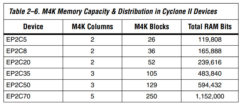
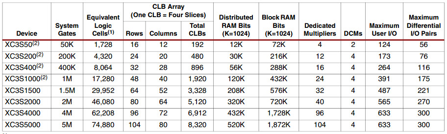
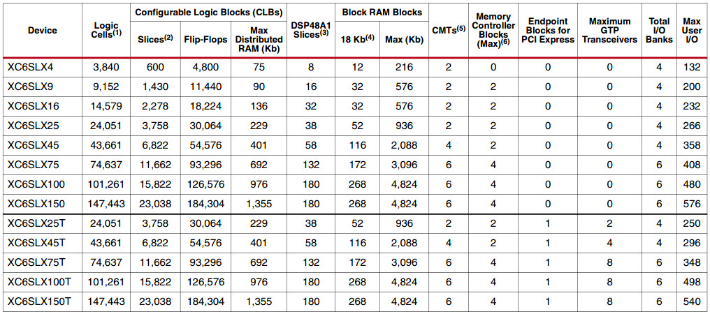
Figure 4 : FPGA memory and logic sizes, Cyclone II (top), Spartan-3 (middle), Spartan-6 (bottom)
From the above tables we can see that the minimum internal memory for these device families varies from 72K to 216K bits, so HD is out :). As i already have a Cyclone II my starting assumption is an FPGA with: 119808 bits, or 14,976 bytes. However, even if we were to reduce the display resolution to 160 x 120 we would only have just enough memory to implement the frame buffer, let alone font data or instruction memory for the processor. Therefore, assuming a simpleCPU_v1d we will need :
VDC memory (8bit) : 160 x 120, "6bit" colour palette : 160 x 120 x 8 = 153,600 bits, 19,200 bytes or 9,600 words
ASCII character memory : 128 x 8 x 8 = 8192 bits, 1024 bytes or 512 words
Graphics tile memory : 128 x 8 x 8 = 8192 bits, 1024 bytes or 512 words
CPU memory : 4096 x 16bit : = 8192 bytes or 4096 words.

Total =  9600 + 512 + 512 + 4096 = 14,720 words or 29,440 byes or 235,520 bits
These memory requirements falls into the low Spartan-6 or midrange Spartan-3 / Cyclone II, which cost approximately £30 to £60, a little more than i would like, however, FPGAs are not cheap. Limiting the display to 64 colours and 160 x 120 pixels may seem quite restrictive, however, the aim of this project is to implement the types of games shown in figure 1, not your typical 3D first person shooter. Yes the Atari 2600 did support 160 x 192 pixels and 128 colours, but to save money and to make life simple, sacrifices need to be made :).
Note, the Cyclone II is still a possibility, but would have to go for a monochrome display.
To simplify FPGA hardware game specific graphics will again be made from 8 x 8 pixel, graphic tiles i.e. so that we can use the same hardware used to process text characters, as shown below:
 |     | |     |                 |     | |     |
 8 4 2 1 8 4 2 1                 8 4 2 1 8 4 2 1
 . . . # # . . .   0x18          . # . . . . # .   0x42
 . . # # # # . .   0x3C          . . # . . # . .   0x24
 . # # # # # # .   0x7E          . # # # # # # .   0x7E
 # # . # # . # #   0xDB          . # . # # . # .   0x5A
 # # # # # # # #   0xFF          # # # # # # # #   0xFF
 . . # . . # . .   0x24          # # # # # # # #   0xFF
 . # . # # . # .   0x5A          . . # . . # . .   0x24
 # . # . . # . #   0xA5          . # . . . . # .   0x42
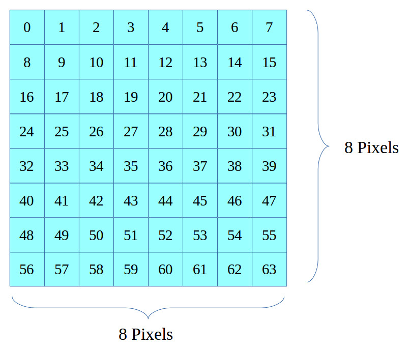
Figure 5 : Tile pixel numbers
This approach is a little limiting, as graphical elements in a game are typically larger than 8 x 8 pixels e.g. only one of the original Space Invader sprites fits into these dimensions. Therefore, "larger tiles" can be made from multiple tiles e.g. the base in Space Invaders as shown below. However, with a little adjustment you can optimise graphical elements to fit into these size constraints. Note, for backgrounds / borders (walls) graphics i.e. graphics that do not move, we can use the "raw write" mode in the VDC to set pixel values, as these pixels will not change during a game.
 |     | |     |                 |     | |     |
 8 4 2 1 8 4 2 1                 8 4 2 1 8 4 2 1
 . . . . . . . .   0x00          . . . . . . . .   0x00
 . . . . . . . .   0x00          . . . . . . . .   0x00
 . . . # # # # #   0x1F          # # # # # . . .   0xF8
 . . # # # # # #   0x3F          # # # # # # . .   0xFC
 . # # # # # # #   0x7F          # # # # # # # .   0xFE
 # # # # # . . .   0xF8          . . . # # # # #   0x1F
 # # # . . . . .   0xE0          . . . . . # # #   0x07
 # # # . . . . .   0xE0          . . . . . # # #   0x07
Simple animations can be implemented by defining a set of tiles for each graphical element e.g. a missile explosion as shown below, and automatically cycling through these.
 |     | |     |                 |     | |     |                |     | |     |                |     | |     |
 8 4 2 1 8 4 2 1                 8 4 2 1 8 4 2 1                8 4 2 1 8 4 2 1                8 4 2 1 8 4 2 1
 . . . . . . . .   0x00          . . . . . . . .   0x00         . . . . . . . .   0x00         . . . . . . . .   0x00
 . . . # . . . .   0x10          . . . . . . . .   0x00         . . . . . . . .   0x00         . . . . . . . .   0x00
 . # . # . # . .   0x54          . . . # . . . .   0x10         . . . # . . . .   0x10         . . . . . . . .   0x00
 . . # # # . . .   0x38          . . # # # . . .   0x38         . . # # # . . .   0x38         . . . # . . . .   0x10
 # # # . # # # .   0xEE          . # # . # # . .   0x6C         . . # # # . . .   0x38         . . . # . . . .   0x10
 . . # # # . . .   0x38          . . # # # . . .   0x38         . . . # . . . .   0x10         . . . . . . . .   0x00
 . # . # . # . .   0x54          . . . # . . . .   0x10         . . . . . . . .   0x00         . . . . . . . .   0x00
 . . . # . . . .   0x10          . . . . . . . .   0x00         . . . . . . . .   0x00         . . . . . . . .   0x00
As with text characters each tile is displayed using a single colour. Therefore, to create a multi-coloured graphic elements, multiple tiles can be overlayed on top of each other e.g. consider a Space Invader with different coloured eyes as shown below. If the left tile is displayed in green and the right tile displayed in red, we have a green, red eyed monster :).
 |     | |     |                 |     | |     |
 8 4 2 1 8 4 2 1                 8 4 2 1 8 4 2 1
 . . . # # . . .   0x18          . . . . . . . .   0x00
 . . # # # # . .   0x3C          . . . . . . . .   0x00
 . # # # # # # .   0x7E          . . . . . . . .   0x00
 # # . # # . # #   0xDB          . . # . . # . .   0x24
 # # # # # # # #   0xFF          . . . . . . . .   0x00
 . . # . . # . .   0x24          . . . . . . . .   0x00
 . # . # # . # .   0x5A          . . . . . . . .   0x00
 # . # . . # . #   0xA5          . . . . . . . .   0x00
With this initial design phase complete its time to implement this VDC on the FPGA.
One of hardest parts of designing any new hardware component is determining what functionality it should support. Especially when you haven't fully defined what its requirement are e.g. deciding what functionality a game needs, when you haven't written the game. Therefore, i decided to start at the VGA interface and work backwards. The VGA interface hardware is relatively simple to implement in an FPGA (Link), as shown in figure 6. Pins 1(R), 2(G) and 3(B) controls each pixel's colour, represented as an analogue voltage: 0v (no colour) to 1.0V (full colour). Pixel selection is controlled via the horizontal (pin 13) and vertical (pin 14) synchronisation control signals i.e. given a fixed scan rate these signals (pulses) define the start of a row and frame updates. The analogue voltages used to define the RGB value are generated by a simple resistor based digital to analogue converter (DAC) (Link) i.e. the 510, 1K, 2K and 4K resistors shown in figure 6. These are combined with a 75 ohm termination resistor within the monitor to form a potential divider circuit. Therefore, by setting the associated digital outputs on the FPGA to a logic 0 (0V) or logic 1 (3.3V) we can generate the required output voltages, as previously discussed in the SimpleCPU_v1d Pong game (Link).
Figure 6 : VGA interface
To develop the initial prototype i used FPGA boards i had to hand, a Digilent Arty board, using an Artix-7 FPGA and a Spartan-3E, using a XC3S500E, as shown in figure 7. Note, these FPGA boards have a lot more memory and logic than required, the Spartan board has a built in VGA connector and uses the same resistor style DAC, but only supports 1bit colour resolution for R, G and B.
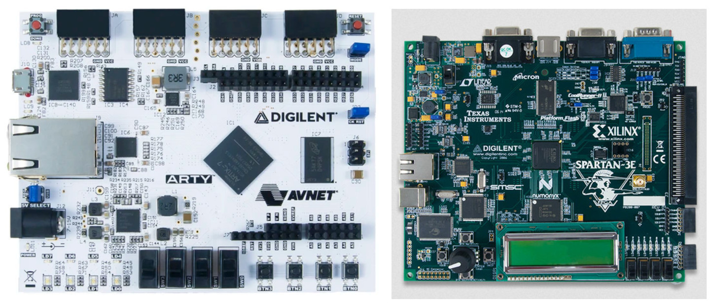
Figure 7 : Prototype FGPA boards, Artix-7 FPGA (left), Spartan-3E (right)
The PMOD connectors for the Arty board are wired as shown below:
 PMOD JA
 -------
 G13 ----------------------------------------------------
 B11 ------------------------------------------------   |
 A11 --------------------------------------------   |   |
 D12 -----------------------------------------  |   |   |
 K16 --------------------------------------  |  |   |   |
 A18 -----------------------------------  |  |  |   |   |
 B18 ------------------------------    |  |  |  |   |   |
 D13 ---------------------------  |    |  |  |  |   |   |
                               |  |    |  |  |  |   |   |
 PMOD JD                       |  |    |  |  |  |   |   |
 -------                       |  |    |  |  |  |   |   |
 F3  ------------------------  |  |    |  |  |  |   |   |
 F4  ---------------------  |  |  |    |  |  |  |   |   |
 D3  ----------------    |  |  |  |    |  |  |  |   |   |
 D4  -------------  |    |  |  |  |    |  |  |  |   |   |
 E2  ----------  |  |    |  |  |  |    |  |  |  |   |   |
 D2  -------  |  |  |    |  |  |  |    |  |  |  |   |   |
           |  |  |  |    |  |  |  |    |  |  |  |   |   |

          4K 2K 1K 500  4K 2K 1K 500  4K 2K 1K 500  82  82
               RED          GREEN         BLUE      VS  HS
This circuit uses 4bits to generate the R, G and B output signals, rather than the 2bits previously discussed. However, i decided to keep this circuit as its easy to build and could allow future improvements. Normal VGA interfaces assume a resolution of 640 x 480 pixels, however, in order to reduce video RAM size this VDC will only support screen resolutions of 160 x 120 pixels. Therefore, i decided to implement a hardware "up-scaler", to automatically scale the image by a factor of 4 i.e. one pixel in the 160 x 120 frame buffer will produce a 4 x 4 pixel on the 640 x 480 display. This does result in "chunky" pixels, but for the types of retro games this system is designed to run thats fine.
Next, i needed to decide how this pixel data was to be stored in memory. This memory could be constructed from 8bit memory locations i.e. each memory location stores data for one pixel. However, to improve memory bandwidth i decided to go for 16bits i.e. each memory transaction reads two pixel values, reducing the time it takes to read data from the frame buffer or write data to it. This raises the question how should RGB data be packets into these 16bit memory locations?
OPTION A
--------
                  pixel 1 data                 |              pixel 0 data               |
 bit15 bit14 bit13 bit12 bit11 bit10 bit9 bit8 | bit7 bit6 bit5 bit4 bit3 bit2 bit1 bit0 |
   X     X     R     R     G     G    B    B   |   X    X    R    R    G    G   B    B   |

 160 x 120 = 19,200 = 9600  x 16bit

 TODO
 unused top two bits can be used to represent layers e.g.
 00 = background
 01 = lower middle
 10 = upper middle
 11 = foreground

OPTION B
--------
                  pixel 1 data                 |              pixel 0 data               |
 bit15 bit14 bit13 bit12 bit11 bit10 bit9 bit8 | bit7 bit6 bit5 bit4 bit3 bit2 bit1 bit0 |
   X     R     R     G     G     G     B    B  |   X    R    R    G    G    G    B    B  |

OPTION C
--------
                  pixel 1 data                 |              pixel 0 data               |
 bit15 bit14 bit13 bit12 bit11 bit10 bit9 bit8 | bit7 bit6 bit5 bit4 bit3 bit2 bit1 bit0 |
   R     R     G     G     G     G     B    B  |   R    R    G    G    G    G    B    B  |

OPTION D
--------
                  pixel 1 data                 |              pixel 0 data               |
 bit15 bit14 bit13 bit12 bit11 bit10 bit9 bit8 | bit7 bit6 bit5 bit4 bit3 bit2 bit1 bit0 |
   R     R     R     G     G     G     B    B  |   R    R    R    G    G    G    B    B  |
Decided to go with option A, 2bits for R, G and B and the unused bits could be used in the next version, version 2, to implement additional functionality e.g. introduce the concept of layers. Therefore, from the previous calculation we need 9600 words for the frame buffer and 2048 words for fonts and tiles, giving a 12K x 16 VDC memory map below:
 VIDEO MEMORY MAP
 ----------------
 12K x 16 - two pixel values per location need 9600 locations per image

                ---------------------
 0x0000 (00000) |                   |
                |   Frame Buffer    |  19,200 B
 0x257F (09599) |                   |
                ---------------------
 0x2580 (09600) |                   |
                |  Fonts and Tiles  |   2176 B
 0x2DFF (11775) |                   |
                ---------------------
 0x2E00 (11776) |                   |
                |        NU         |   512 B
 0x2FFF (12287) |                   |
                ---------------------

 ADDRESS
 -------
  13   12   11   10   9   8   7  6  5  4 3 2 1 0
 8192 4096 2048 1024 512 256 128 64 32 16 8 4 2 1
    1    0    0    1   0   1   0  1  1  1 1 1 1 1   = 9599
    1    0    0    1   0   1   1  0  0  0 0 0 0 0   = 9600
    1    0    1    1   1   1   1  1  1  1 1 1 1 1   = 12287
Using this 2+2+2 (6bit) colour palette the following "main" colour codes can be used:
 PIXEL DATA FORMAT
 -----------------
                  pixel 1 data                 |              pixel 0 data               |
 bit15 bit14 bit13 bit12 bit11 bit10 bit9 bit8 | bit7 bit6 bit5 bit4 bit3 bit2 bit1 bit0 |
   X     X     R     R     G     G    B    B   |   X    X    R    R    G    G   B    B   |

 COLOURS
 -------
             XXRR GGBB
 RED         0011 0000 = 0x30
 GREEN       0000 1100 = 0x0C
 BLUE        0000 0011 = 0x03
 YELLOW      0011 1100 = 0x3C
 ORANGE      0011 0100 = 0x34
 TURQUOISE   0000 1111 = 0x0F
 LIGHT_BLUE  0000 0111 = 0x07
 LIGHT_GREEN 0000 1101 = 0x0D
 LIME_GREEN  0001 1100 = 0x1C
 PURPLE      0001 0011 = 0x13
 PINK        0011 0011 = 0x33
 SCARLET     0011 0001 = 0x31
 GREY        0001 0101 = 0x15
 LIGHT_GREY  0010 1010 = 0x2A
 BLACK       0000 0000 = 0x00
 WHITE       0011 1111 = 0xFF
Figure 8 : Colour codes
The VGA specification dates back to the age of CRT displays, raster scan (Link) and when an image was produced on a display using an electron beam and a phosphor coated screen. Those day have passed and we now typically use an LED display, however, we still need to generate the horizontal (Hsync) and vertical (Vsync) timing control signals associated with this raster scan. The speed of the electron beam as it travels across the display is determined by its refresh frequency, for a typical 640 x 480 display this is 60Hz, but other sizes and speeds were used: (Link). To understand these signals we need to understand how the old CRT displays functioned, as illustrated in figure 9.
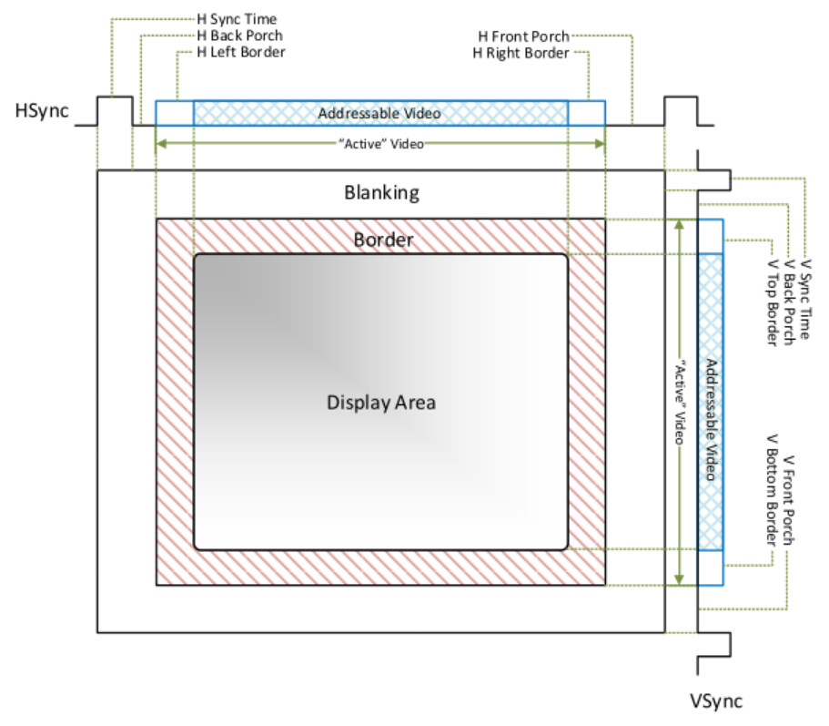
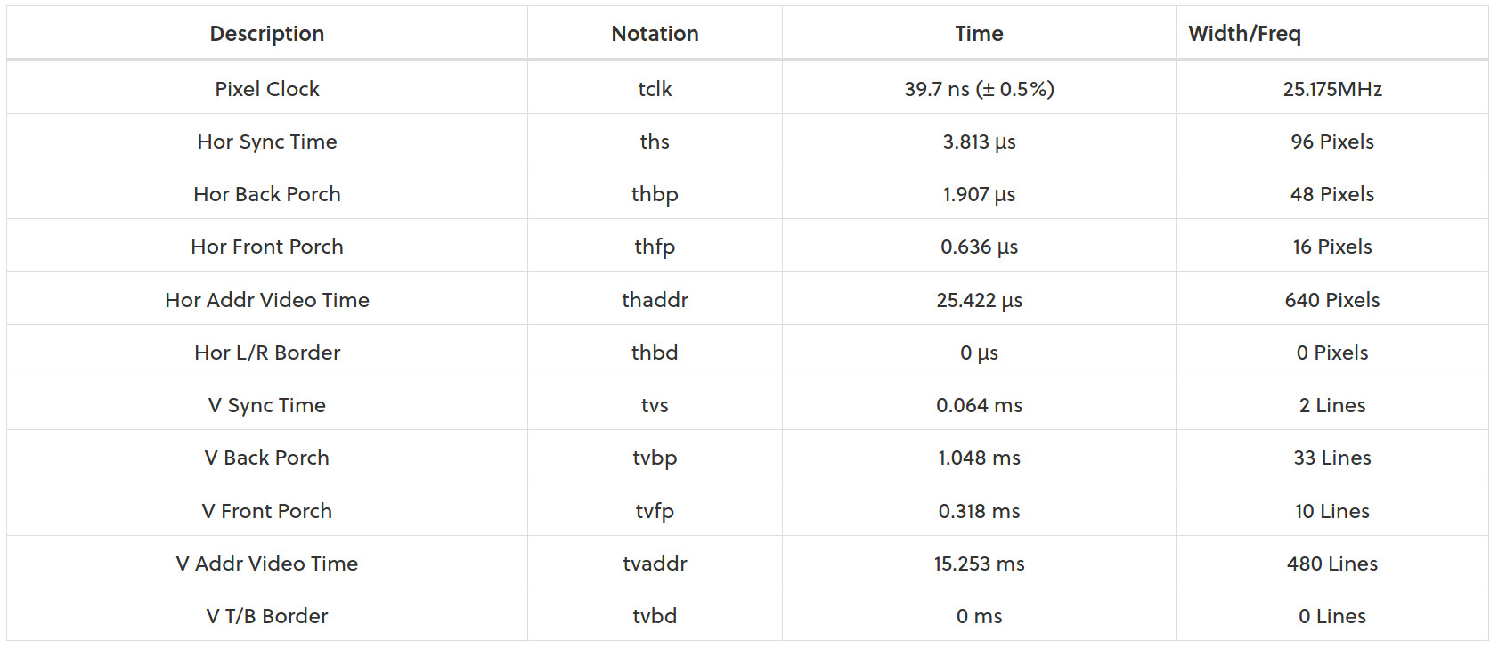
Figure 9 : CRT timimgs (source Digilent: Link)
From this picture you can see that the screen is actually bigger than 640 x 480 pixels, and is actually 800 x 525 pixels in size. However, some of these "pixels" are used in the fly-back period when the electron gun on the old CRT displays returned back to the start of the next line i.e. the blanking sections. The border sections of the display are also not visible as these were associated with the curved edges of the CRT tube. Therefore, only the central 640 x 480 region was viewable. However, when calculating the pixel clock speed we need to consider all of these regions and their associated timings:
Pixel clock speed = 1/ ((640+96+48+16) x (480+2+33+10) x 60) = 39.7ns = 25MHz (approx)
Using a 25MHz clock and a counter we can generate the Hsync timing signal i.e. a free running counter + some decode logic to generate the required output pulses during the specified count values:
 HORIZONTAL COUNT
 ----------------
                      640 ACTIVE
 _______    -------------------------------         ______
 |     |____-                             -_________|    |
 0    96    144                         784      799|0
We can also implement the Vsync timing signal in the same way, but this time counting the number of horizontal lines displayed:
 VERTICAL COUNT
 --------------
                   480 ACTIVE
 ____   -------------------------------         ____
 |  |___-                             -_________|  |
 0  2   35                          515      524|0
Then its just the "simple" matter of setting the output pins shown in figure 6 to the correct values to produce the right RGB voltages on each pixel clock cycle i.e. read the frame buffer and output the 2bit RGB values. Note, the slight additional complexities are that each pixel value is outputted four times i.e. automatic up-scaling in hardware from 160 x 120 to 640 x 480, and each memory location stores two pixel values, so we only need to read the frame buffer at half the pixel clock speed. The top level hardware architecture used to implement this in the VDC is shown in figure 10.
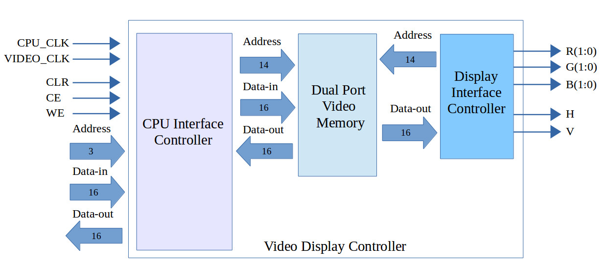
Figure 10 : VDC hardware architecture
The frame buffer in the VDC uses dual port memory allowing the display interface and the processor interface to operate in parallel i.e. the video hardware can read RGB data to be displayed, whilst the processor is updating the same frame buffer with new tile data. The processor interface to the VDC control logic has the following memory mapped regisers:
 REGISTER MAP
 ------------
 ADDR      WRITE               READ
 ----      -----               ----
 0      control reg         status reg
 1      src addr reg        src addr reg
 2      data_in reg         data out reg
 3      colour reg          tile position
 4      dest addr reg       dest addr reg
 5      x position          x position
 6      y position          y position
 7      nu                  nu
VDC functions are triggered by writing a command code to the control register and detecting when it has completed the specified task via the status register.
 COMMAND REGISTER           STATUS REGISTER
 ----------------           ---------------
 B7 : nu                    B7 : nu
 B6 : nu                    B6 : nu
 B5 : nu                    B5 : nu
 B4 : nu                    B4 : nu
 B3 : function b3           B3 : nu
 B2 : function b2           B2 : vga idle
 B1 : function b1           B1 : cpu idle
 B0 : function b0           B0 : ram idle
Functions supported by the VDC and their command codes are listed below:
 FUNCTION
 --------
 0 : write data   - dest address + data
 1 : write data   - dest address + data + data ...             (address auto increment)
 2 : read  data   - src address + data
 3 : read data    - src address + data + data ...              (address auto increment)
 4 : block copy   - src adddress + dest address + end address  (block copy)
 5 : block write  - dest adddress + end address + colour       (block init)
 6 : draw tile    - src address + x pos + y pos + colour       (tile 8x8)
 7 : draw pixel   - x pos + y pos + colour                     (single pixel)
 8 : overlay tile - src address + x pos + y pos + colour       (tile 8x8)
 9 : delete tile  - src address + x pos + y pos + colour       (tile 8x8)
 F : nop
Within the video memory the address range 0x2580 to 0x2DFF store the bitmap values for each text character and any graphical elements used in the program. The full 7bit ASCII character set is defined starting at address 0x2580 i.e. the NULL character, and finishing at address 0x277C i.e. the DEL character. Non-printable control characters are not supported i.e. DEL does not delete, LF does not perform a line feed. This data is defined in a text file and is automatically converted into a memory initialisation file used by the FPGA tools. An example section is shown below:
...

{ 0x00, 0x00, 0x63, 0x6B, 0x7F, 0x7F, 0x36, 0x00 },   // U+0077 (w)      0952
{ 0x00, 0x00, 0x63, 0x36, 0x1C, 0x36, 0x63, 0x00 },   // U+0078 (x)      0960
{ 0x00, 0x00, 0x33, 0x33, 0x33, 0x3E, 0x30, 0x1F },   // U+0079 (y)      0968
{ 0x00, 0x00, 0x3F, 0x19, 0x0C, 0x26, 0x3F, 0x00 },   // U+007A (z)      0976
{ 0x38, 0x0C, 0x0C, 0x07, 0x0C, 0x0C, 0x38, 0x00 },   // U+007B ({)      0984
{ 0x18, 0x18, 0x18, 0x00, 0x18, 0x18, 0x18, 0x00 },   // U+007C (|)      0992
{ 0x07, 0x0C, 0x0C, 0x38, 0x0C, 0x0C, 0x07, 0x00 },   // U+007D (})      1000
{ 0x6E, 0x3B, 0x00, 0x00, 0x00, 0x00, 0x00, 0x00 },   // U+007E (~)      1008
{ 0x00, 0x00, 0x00, 0x00, 0x00, 0x00, 0x00, 0x00 },   // U+007F          1016    7F-20 = 5F = 95x4 + 9728  = 10108

#  |     | |     |
#  8 4 2 1 8 4 2 1
#  . . . # # . . .
#  . . # # # # . .
#  . # # # # # # .
#  # # . # # . # #
#  # # # # # # # #
#  # . # # . # . #
#  # . . . . . . #
#  . # . . . . # .
{ 0x18, 0x3C, 0x7E, 0xDB, 0xFF, 0xB5, 0x81, 0x42 }    // U+0080          1020   10112

#  |     | |     |
#  8 4 2 1 8 4 2 1
#  . . . # # . . .
#  . . # # # # . .
#  . # # # # # # .
#  # # . # # . # #
#  # # # # # # # #
#  . . # . . # . .
#  . # . # # . # .
#  # . # . . # . #
{ 0x18, 0x3C, 0x7E, 0xDB, 0xFF, 0x24, 0x5A, 0xA5 }    // U+0081          1028   10116

...
Note, as the video frame buffer is implemented in the FPGA, the same FPGA software tools can be used to initialise this memory i.e. when the FPGA is configured the frame buffer can be initialised to the game's intro screen, removing the need to implement this in software. The only downside is that this data is not redisplayed when the processor is reset i.e. its only loaded into memory during the FPGA configuration process.
With the initial hardware and software interfaces defined its time to implement this VDC on the FPGA.
To save time the initial VDS prototype was implemented as a VHDL component, drawing the schematics would just be tooo much fun :). This component was imported into a Xilinx ISE project, the VHDL entity, component symbol and top level ISE project schematic are shown in figure 11.
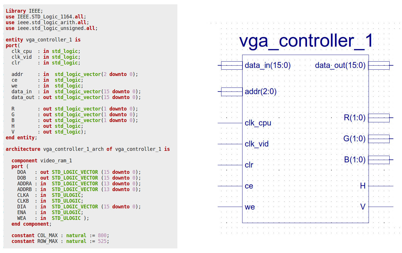
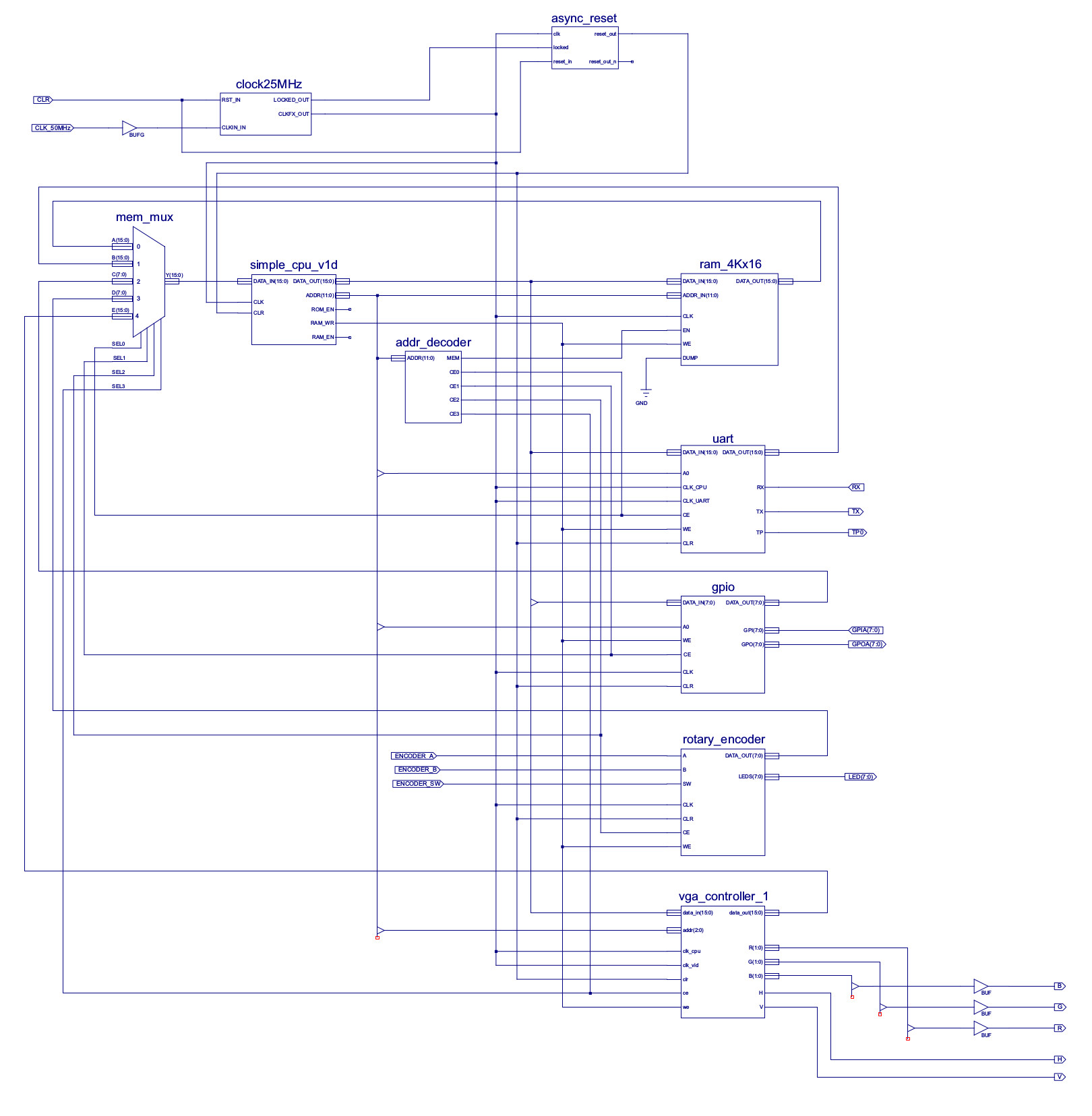
Figure 11 : VDC symbol (top), Top-level schematic (bottom)
The top level system schematic shown in figure 11 also contains GPIO, Serial and a rotary encoder peripheral device. The GPIO and Serial were included for debugging i.e. print debug messages to a terminal or turning on/off LEDs. The rotary encoder is present on the Spartan-3E board and can be used to implement a simple controller i.e. move the player sprite left/right and fire. For more detail on the rotary encoder hardware refer to: (Link).
To implement the top level VDC architecture shown in figure 10, i implemented a 12K x 16, dual-port memory from twelve 4K x 4bit BlockRAM components:
    BANK A            BANK B           BANK C
    4Kx16             4Kx16            4Kx16
 blkRamA0(4Kx4)    blkRamB0(4Kx4)    blkRamC0(4Kx4)
 blkRamA1(4Kx4)    blkRamB1(4Kx4)    blkRamC1(4Kx4)
 blkRamA2(4Kx4)    blkRamB2(4Kx4)    blkRamC2(4Kx4)
 blkRamA3(4Kx4)    blkRamB3(4Kx4)    blkRamC3(4Kx4)
      ||                ||                ||
     4Kx16             4Kx16             4Kx16

 ADDR
 15    14    13   12   11   10   9   8   7   6  5  4  3 2 1 0
 32768 16384 8192 4096 2048 1024 512 256 128 64 32 16 8 4 2 1

 ADDRB 16Bit
 11 : 0 = ADDR
 13 12
 0  0   = BANK 0
 0  1   = BANK 1
 1  0   = BANK 2
 1  1   = NU
This memory implements the frame buffer and character/tile memory and is shared between the CPU interface controller and the display interface controller. These two controllers run in parallel accessing this dual port memory. The display interface controller is shown in figure 12. Basically just a handful of counters, generating the H and V timing signals and the address of pixel data in the frame buffer. These counters are clocks at the pixel clock speed i.e. 25MHz.
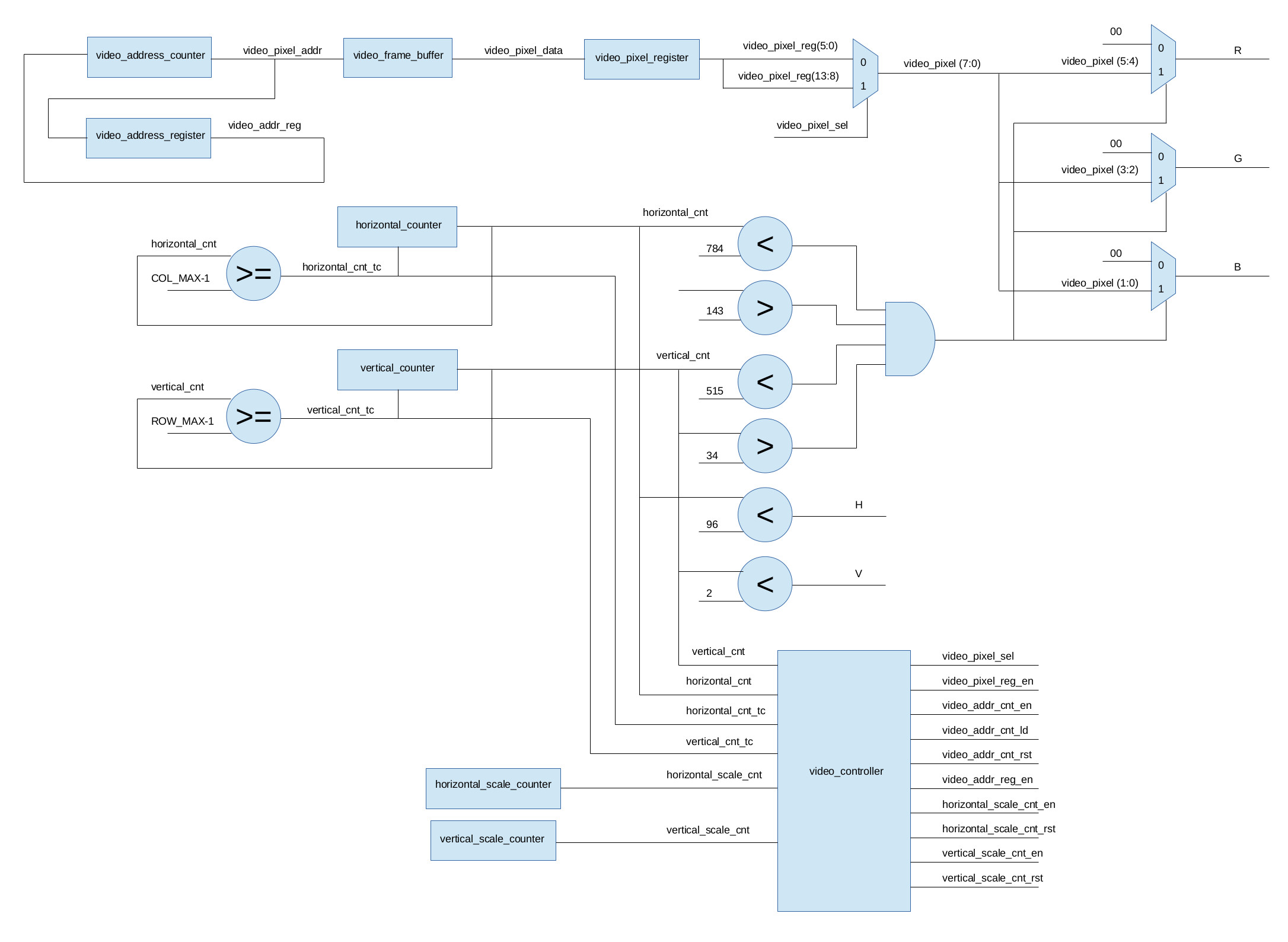
Figure 12 : Display interface controller block diagram
The CPU interface controller shown in figure 13 is a little more complex implementing the desired command functions.
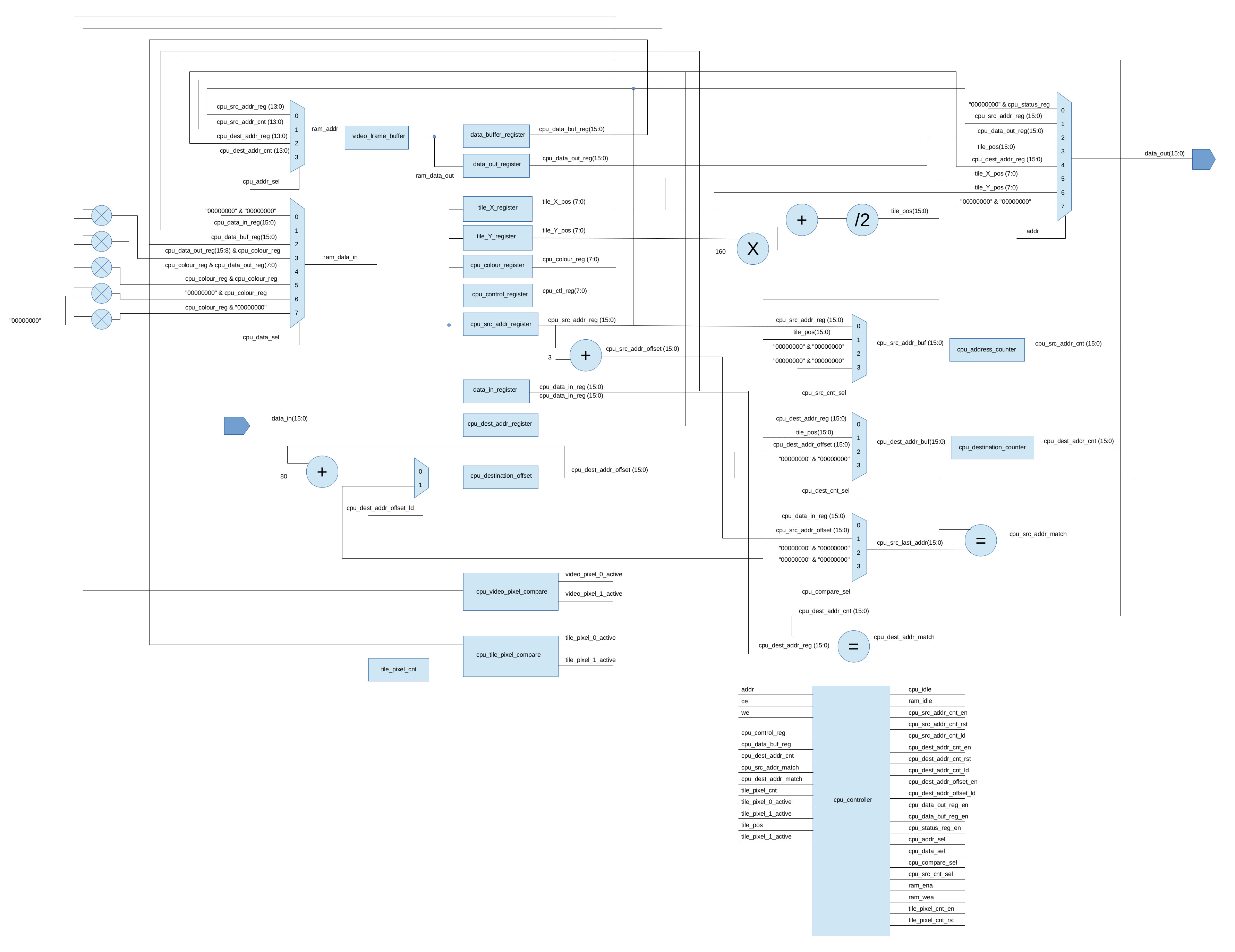
Figure 13 : CPU interface controller block diagram
NEED TO COMPLETE
A common method of organising the graphical elements used in older 8 bit games machines was through the use of sprites (Link), typically these were implemented in dedicated hardware to reduce processing loads. I did consider doing this, however, to keep things simple, version 1 of the VDC is going to use software based sprites. Each sprite is defined using a 16 word data structure as shown below:
 0  : FLAGS : VISIBLE : AUTO : TILE_INC : TILE_NUMBER (1:1:1:3)
 1  : TILE_ADDRESS_0
 2  : TILE_ADDRESS_1
 3  : TILE_ADDRESS_2
 4  : TILE_ADDRESS_3
 5  : TILE_ADDRESS_4
 6  : TILE_ADDRESS_5
 7  : TILE_ADDRESS_6
 8  : TILE_ADDRESS_7
 9  : BG COLOUR : FG COLOUR   (8:8)
 10 : XPOS : YPOS             (8:8)
 11 : XOFFSET : YOFFSET       (8:8)
 12 : HB_XMAX : HB_XMIN       (8:8)
 13 : HB_YMAX : HB_YMIN       (8:8)
 14 : LT_XMAX : LT_XMIN       (8:8)
 15 : LT_YMAX : LT_YMIN       (8:8)
These fields define the follow sprite attributes:
 VISIBLE      : 0 = not visible, 1 = visible
 AUTO         : 0 = direction fixed, 1 = auto direction reversed on limit collisions
 TILE_INC     : 0 = fixed tile number, 1 = auto incrementing tile number when displayed
 TILE_NUMBER  : current tile address 0 - 7, 3bit value, overflow back to 0.
 TILE ADDRESS : pointers 0-7 to Font/Tile addresses in video memory.
 BG_COLOUR    : background colour, 8bit value
 FG_COLOUR    : foreground colour, 8bit value
 XPOS         : x position of top left pixel of tile, 8bit value
 YPOS         : y position of top left pixel of tile, 8bit value
 XOFFSET      : x offset, signed 8bit value
 YOFFSET      : y offset, signed 8bit value
 HB_XMAX      : hit-box, x max, 8bit value
 HB_XMIN      : hit-box, x min, 8bit value
 HB_YMAX      : hit-box, y max, 8bit value
 HB_YMIN      : hit-box, y min, 8bit value
 LT_XMAX      : limit, x max, 8bit value
 LT_XMIN      : limit, x min, 8bit value
 LT_YMAX      : limit, y max, 8bit value
 LT_YMIN      : limit, y min, 8bit value
Each sprites is associated with eight possible tiles. This may be slight overkill, but the aim was to simplify basic animations i.e. if the TILE_INC flag is set each time the sprite is displayed (draw or overlay) the TILE_NUMBER field is incremented. This field points to the current tile address field, allowing the sprite to automatically cycle through a sequence of tiles. The thought was that for games such as Combat this would allow a tank to have eight rotational images i.e. allow the game to animate 45 degree rotations. This data structure also contains the sprite's XY display position (top left corner), its XY offset used in a move and its XY limits. If a move command would exceed these limits the XPOS or YPOS will either not be updated, or automatically reversed i.e. move the sprite away from this limit (border/edge). This selection is determined by the AUTO flag. Finally, the sprite's hit-box field defines offsets in the 8 x 8 tile, reducing the active area during sprite collision calculations. This data structure is initialised using the initialize_sprite macro, being passed 26 parameters, as shown below:
# VISIBLE, AUTO TILE_INC TILE_NUMBER, TILE_ADDR_0, TILE_ADDR_1, TILE_ADDR_2, TILE_ADDR_3, TILE_ADDR_4, TILE_ADDR_5, TILE_ADDR_6, TILE_ADDR_7,
# 1        2    3        4            5            6            7            8            9            10           11           12

# BG COLOUR, FG COLOUR, XPOS, YPOS, XOFFSET, YOFFSET, HB_XMAX, HB_XMIN, HB_YMAX, HB_YMIN, LT_XMAX, LT_XMIN, LT_YMAX, LT_YMIN,
# 13         14         15    16    17       18       19       20       21       22       23       24       25       26

alien_sprite_data:
  initialize_sprite( 1, 1, 1, 0, SPRITE_ALIEN_1_DOWN, SPRITE_ALIEN_1_UP, SPRITE_ALIEN_1_DOWN, SPRITE_ALIEN_1_UP,
                              SPRITE_ALIEN_1_DOWN, SPRITE_ALIEN_1_UP, SPRITE_ALIEN_1_DOWN, SPRITE_ALIEN_1_UP,
                              BLACK, GREEN, 82,  15, RIGHT, DOWN, 7, 0, 7, 0, MAX_X_LIMIT, eval( MIN_X_LIMIT + 2 ), eval( MAX_Y_LIMIT - 18 ), eval( MIN_Y_LIMIT + 2 ) )

  initialize_sprite( 1, 1, 1, 0, SPRITE_ALIEN_2_DOWN, SPRITE_ALIEN_2_UP, SPRITE_ALIEN_2_DOWN, SPRITE_ALIEN_2_UP,
                              SPRITE_ALIEN_2_DOWN, SPRITE_ALIEN_2_UP, SPRITE_ALIEN_2_DOWN, SPRITE_ALIEN_2_UP,
                              BLACK, YELLOW, 72,  25, LEFT, DOWN, 7, 0, 7, 0, MAX_X_LIMIT, eval( MIN_X_LIMIT + 2 ), eval( MAX_Y_LIMIT - 18 ), eval( MIN_Y_LIMIT + 2 ) )

  initialize_sprite( 1, 1, 1, 0, SPRITE_ALIEN_3_DOWN, SPRITE_ALIEN_3_UP, SPRITE_ALIEN_3_DOWN, SPRITE_ALIEN_3_UP,
                              SPRITE_ALIEN_3_DOWN, SPRITE_ALIEN_3_UP, SPRITE_ALIEN_3_DOWN, SPRITE_ALIEN_3_UP,
                              BLACK, SCARLET, 62,  35, LEFT, UP, 7, 0, 7, 0, MAX_X_LIMIT, eval( MIN_X_LIMIT + 2 ), eval( MAX_Y_LIMIT - 18 ), eval( MIN_Y_LIMIT + 2 ) )
  ...
The aim is to construct a data structure i.e. a class, that contains all the required information for each sprite. These sprites are then controlled using a set of high level macros to implement the desired game behaviours. The demo "Space Invader" code is shown below:
# =============================================================================================================
# *
# * Copyright (c) Mike
# *
# * File Name: spaceInvadersDemo.asm
# *
# * Version: V1.0
# *
# * Release Date:
# *
# * Author(s): M.Freeman
# *
# * Description: space invaders test code
# *
# * Conditions of Use: THIS CODE IS COPYRIGHT AND IS SUPPLIED "AS IS" WITHOUT WARRANTY OF ANY KIND, INCLUDING,
# *                    BUT NOT LIMITED TO, ANY IMPLIED WARRANTY OF MERCHANTABILITY AND FITNESS FOR A
# *                    PARTICULAR PURPOSE.
# *
# * Notes:
# *
# =============================================================================================================

start:
    clear_screen( 0 )
    run( draw_game_screen )
    run( draw_intro_screen )

    sleep( 100 )

    clear_screen( 0 )
    run( draw_game_screen )

    set( player_score, 0 )
    set( player_lives, 0 )

loop:
    overlay_sprite( alien_sprite_data, 0 )
    overlay_sprite( alien_sprite_data, 1 )
    overlay_sprite( alien_sprite_data, 2 )
    overlay_sprite( alien_sprite_data, 3 )
    overlay_sprite( alien_sprite_data, 4 )
    overlay_sprite( alien_sprite_data, 5 )
    overlay_sprite( alien_sprite_data, 6 )

    draw_sprite( player_sprite_data, 0 )

    run( alien_missile_update )
    overlay_sprite( missile_sprite_data, 0 )

    run( player_missile_update )
    overlay_sprite( missile_sprite_data, 1 )

    run( update_explosion )
    overlay_sprite( explosion_sprite_data, 0 )

    sleep( 4 )

    clear_sprite( alien_sprite_data, 0 )
    clear_sprite( alien_sprite_data, 1 )
    clear_sprite( alien_sprite_data, 2 )
    clear_sprite( alien_sprite_data, 3 )
    clear_sprite( alien_sprite_data, 4 )
    clear_sprite( alien_sprite_data, 5 )
    clear_sprite( alien_sprite_data, 6 )

    clear_sprite( player_sprite_data, 0 )
    clear_sprite( missile_sprite_data, 0 )
    clear_sprite( missile_sprite_data, 1 )
    clear_sprite( explosion_sprite_data, 0 )

update_aliens:
    move_sprite( alien_sprite_data, 0 )
    move_sprite( alien_sprite_data, 1 )
    move_sprite( alien_sprite_data, 2 )
    move_sprite( alien_sprite_data, 3 )
    move_sprite( alien_sprite_data, 4 )
    move_sprite( alien_sprite_data, 5 )
    move_sprite( alien_sprite_data, 6 )

    move_sprite( missile_sprite_data, 0 )
    move_sprite( missile_sprite_data, 1 )

    set( sprite_collision. 0 )

    collision_sprite( base_sprite_data, 0, missile_sprite_data, 0 )
    collision_sprite( base_sprite_data, 1, missile_sprite_data, 0 )
    collision_sprite( base_sprite_data, 2, missile_sprite_data, 0 )
    collision_sprite( base_sprite_data, 3, missile_sprite_data, 0 )
    collision_sprite( base_sprite_data, 4, missile_sprite_data, 0 )
    collision_sprite( base_sprite_data, 5, missile_sprite_data, 0 )
    collision_sprite( base_sprite_data, 6, missile_sprite_data, 0 )
    collision_sprite( base_sprite_data, 7, missile_sprite_data, 0 )

    ifClr( sprite_collision, ANY, test_player_hit )

    turn_off_sprite( missile_sprite_data, 0 )

test_player_hit:
#	        VAR          0 =  move,   1 = hit,    2 = explosion
    ifTest( player_mode, player_move, player_hit, player_explode )

player_move:
    move_sprite( player_sprite_data, 0 )
    set( sprite_collision, 0 )
    collision_sprite( player_sprite_data, 0, missile_sprite_data, 0 )

    ifClr( sprite_collision, ANY, test_alien_hit )

    set( player_mode, 1 )

test_alien_hit:
    set( sprite_collision, 0 )

    collision_sprite( alien_sprite_data, 0, missile_sprite_data, 1 )
    collision_sprite( alien_sprite_data, 1, missile_sprite_data, 1 )
    collision_sprite( alien_sprite_data, 2, missile_sprite_data, 1 )
    collision_sprite( alien_sprite_data, 3, missile_sprite_data, 1 )
    collision_sprite( alien_sprite_data, 4, missile_sprite_data, 1 )
    collision_sprite( alien_sprite_data, 5, missile_sprite_data, 1 )
    collision_sprite( alien_sprite_data, 6, missile_sprite_data, 1 )

    ifClr( sprite_collision, ANY, test_alien_miss )

    run( inc_player_score )
    turn_off_sprite( missile_sprite_data, 1 )
    turn_on_sprite( explosion_sprite_data, 0 )

test_alien_miss:
    goto( loop )

player_hit:
    increment_sprite( player_sprite_data, 0 )

    run( dec_player_lives )
    set( player_mode, 2 )
    goto( loop )

player_explode:
    get_sprite( player_sprite_data, 0 )
    ifClr( sprite_pntr, SPRITE_TILE_NUMBER_MASK, player_restart )
    increment_sprite( player_sprite_data, 0 )
    goto( loop )

player_restart:
    set( player_mode, 0 )
    goto( loop )

trap:
    goto( trap )
The intention is to try to develop a range of general purpose, high-level macros that will simplify the development of simple games. Game specific behaviours would still need to be implemented in assembly code, but i'm looking to get the main-loop fully macro based. The macros so far:
GOTO
goto( ADDR ) : replaces an assembly language JMP instruction to match macro format, reto, basic :), simply jump to label (address).
RUN
run( SUBROUTINE ) : replaces an assembly language CALL instruction to match macro format.
SET
set( VARIABLE, VAL ) : stores the 8bit signed constant VAL to a VARIABLE stored in memory.
CLR
set( VARIABLE ) : stores the value 0 to a VARIABLE stored in memory. Can perform the same function is using the SET macro, include for completeness.
SLEEP
sleep( VAL ) : implemented by a software time delay subroutine i.e. blocking. VAL is an unsigned 16bit constant. Time delay = VAL * 0.2 seconds.
CLEAR SCREEN
clear_screen( COLOUR ) : uses the block write command in the VDC to clear the screen i.e. sets each pixel from address 0 to MAX_ADDRESS to the constant COLOUR. COLOUR codes defined in figure 8.
GET SPRITE
get_sprite( BASE, OFFSET ) : generate the base address of a sprite's data structure. The constant BASE is the address of the first sprite in a sprite list. The constant OFFSET is an index into this list i.e. address generated is BASE + (OFFSET*16), this address is stored in the variable: sprite_pntr. Used in combination with IF macros to test the visibility or active tile.
SET SPRITE
set_sprite( BASE, OFFSET, VAL ) : set the TILE_NUMBER of the selected sprite to the 3bit unsigned constant VAL. The constant BASE is the address of the first sprite in a sprite list. The constant OFFSET is an index into this list i.e. address generated is BASE + (OFFSET*16). The TILE_NUMBER value is the index into the TILE_ADDRESS(0:7) array, selecting the tile used by DRAW and OVERLAY macros. Note, the display is not updated by this macro, it only updates the sprite's data structure.
INCREMENT SPRITE
get_sprite( BASE, OFFSET ) : similar to the SET_SPRITE macro, but increments the TILE_NUMBER of the selected sprite. The constant BASE is the address of the first sprite in a sprite list. The constant OFFSET is an index into this list i.e. address generated is BASE + (OFFSET*16). Note, TILE_NUMBER is a 3bit value, will overflow back to 0 i.e. will cycle through sprite tiles. Note, the display is not updated by this macro, it only updates the sprite's data structure.
TURN OFF SPRITE
turn_off_sprite( BASE, OFFSET ) : set the VISIBLE flag of the selected sprite to 0 i.e. the selected sprite will not be drawn by the DRAW or OVERLAY macros. The constant BASE is the address of the first sprite in a sprite list. The constant OFFSET is an index into this list i.e. address generated is BASE + (OFFSET*16). Note, the display is not updated by this macro, it only updates the sprite's data structure.
TURN ON SPRITE
turn_on_sprite( BASE, OFFSET ) : set the VISIBLE flag of the selected sprite to 1 i.e. the selected sprite will be drawn by the DRAW or OVERLAY macros. The constant BASE is the address of the first sprite in a sprite list. The constant OFFSET is an index into this list i.e. address generated is BASE + (OFFSET*16). Note, the display is not updated by this macro, it only updates the sprite's data structure.
DRAW SPRITE
draw_sprite( BASE, OFFSET ) : write sprite tile data into frame buffer i.e. overwrite frame buffer data with sprite bitmap. The tile position is determined by XPOS and YPOS. Active tile pixel elements are set to FG_COLOUR, zero value tile pixel elements are set to 0 i.e. BLACK. Note, BG_COLOUR is not used and no boundary limit checks are performed at this time i.e. assuming a BLACK background colour for the moment. The constant BASE is the address of the first sprite in a sprite list. The constant OFFSET is an index into this list i.e. address generated is BASE + (OFFSET*16).
OVERLAY SPRITE
overlay_sprite( BASE, OFFSET ) : the same as the DRAW SPRITE macro, except that zero value tile pixel elements are not written to the frame buffer i.e. the original frame buffer pixel values are preserved.
POSITION SPRITE
position_sprite( BASE, OFFSET, XVAL, YVAL ) : set the XPOS and YPOS variables to the unsigned 8bit constants XVAL and YVAL. Used by the DRAW or OVERLAY macros. The constant BASE is the address of the first sprite in a sprite list. The constant OFFSET is an index into this list i.e. address generated is BASE + (OFFSET*16). Note, the display is not updated by this macro, it only updates the sprite's data structure.
OFFSET SPRITE
offset_sprite( BASE, OFFSET, XVAL, YVAL ) : set the XOFFSET and YOFFSET variables to the signed 8bit constants XVAL and YVAL. Used by the DRAW or OVERLAY macros. The constant BASE is the address of the first sprite in a sprite list. The constant OFFSET is an index into this list i.e. address generated is BASE + (OFFSET*16). Note, the display is not updated by this macro, it only updates the sprite's data structure.
CLEAR SPRITE
clear_sprite( BASE, OFFSET ) : uses OVERLAY macro. Active tile pixel elements are set to BG_COLOUR colour, zero value tile pixel elements are not written to the frame buffer. The constant BASE is the address of the first sprite in a sprite list. The constant OFFSET is an index into this list i.e. address generated is BASE + (OFFSET*16).
MOVE SPRITE
move_sprite( BASE, OFFSET ) : XPOS and YPOS incremented by XOFFSET and YOFFSET. Hit-box (HB_XMAX, HB_XMIN, HB_YMAX HB_YMIN) then checked against limits (LT_XMAX, LT_XMIN, LT_YMAX, LT_YMIN). If limits exceeded and AUTO flag set, direction automatically revered, such that sprite moves away from board/edge/limit, otherwise the axis where a limit would be exceeded (XPOS/YPOS) is not updated. The constant BASE is the address of the first sprite in a sprite list. The constant OFFSET is an index into this list i.e. address generated is BASE + (OFFSET*16). Note, sprite is not moved by this macro, it only updates its data structure.
COLLISION SPRITE
collision_sprite( BASE0, OFFSET0, BASE1, OFFSET1 ) : hit-boxes of two sprites are tested to see if they overlap. If hit-boxes do overlap the sprite_collision variable is set to 1, otherwise the sprite_collision variable is not updated. The constants BASE0/BASE1 are the addresses of the first sprite in a sprite list. The constants OFFSET0/OFFSET1 is an index into these lists i.e. address generated is BASE + (OFFSET*16).
IF CLR
ifClr( VARIABLE, MASK, ADDR ) : perform a bitwise AND with an 8bit constant MASK and a VARIABLE stored in memory. If zero jump to specified address, else perform next macro.
IF SET
ifSet( VARIABLE, MASK, ADDR ) : perform a bitwise AND with an 8bit constant MASK and a VARIABLE stored in memory. If not zero jump to specified address, else perform next macro.
IF TEST
ifTest( VARIABLE, ADDR0, ADDR1, ADD2 ... ) : test the value of a VARIABLE stored in memory. Macro can specify up to eight branch addresses i.e. tests is the result is 0,1,2,3,4,5,6 or 7, the first address corresponding to a zero result, then the address for a result of one, a result of two etc. If no match, then perform next macro. Note, must include at least one branch address, addresses for unused tests do not need to be included.
The "cut and paste" power of the M4 pre-processor has also been used to replace constant / addresses and other data values with human readable names, selected examples shown below:
# ------------
# - CONSTANT -
# ------------

define(MAX_X_LIMIT, `160')
define(MAX_Y_LIMIT, `120')
define(MIN_X_LIMIT, `8')
define(MIN_Y_LIMIT, `16')

define(MIN_ADDRESS, `0')
define(MAX_ADDRESS, `eval( ((160 * 120)/2) - 1) ')

define(DOWN, `1')
define(UP, `255')
define(LEFT, `255')
define(RIGHT, `1')
...

# ----------------
# - COLOUR CODES -
# ----------------

define(RED, `0x30')
define(GREEN, `0x0C')
define(BLUE, `0x03')
define(YELLOW, `0x3C')
define(ORANGE, `0x34')
define(TURQUOISE, `0x0F')
define(LIGHT_BLUE, `0x07')
define(LIGHT_GREEN, `0x0D')
...

# -----------------------
# - VIDEO COMMAND CODES -
# -----------------------

define(WRITE_PIXEL, `0x00')
define(WRITE_PIXEL_AUTO_INC, `0x01')
define(READ_PIXEL, `0x02')
define(READ_PIXEL_AUTO_INC, `0x03')
define(BLOCK_COPY, `0x04')
define(BLOCK_WRITE, `0x05')
define(DRAW_TILE, `0x06')
define(DRAW_PIXEL, `0x07')
define(OVERLAY_TILE, `0x08')
...

# ----------------------------
# - CHARACTER TILE ADDRESSES -
# ----------------------------

define(<_CHAR, `eval( 9728 + 28*4 )')
define(=_CHAR, `eval( 9728 + 29*4 )')
define(>_CHAR, `eval( 9728 + 30*4 )')
define(?_CHAR, `eval( 9728 + 31*4 )')
define(@_CHAR, `eval( 9728 + 32*4 )')
define(A_CHAR, `eval( 9728 + 33*4 )')
...

# -------------------------
# - GRAHIC TILE ADDRESSES -
# -------------------------

define(SPRITE_ALIEN_1_DOWN, `10112' )
define(SPRITE_ALIEN_1_UP, `10116' )

define(SPRITE_EXPLOSION_1, `10180' )
define(SPRITE_EXPLOSION_2, `10184' )
define(SPRITE_EXPLOSION_3, `10188' )
define(SPRITE_EXPLOSION_4, `10192' )
define(SPRITE_EXPLOSION_5, `10196' )
...

# -----------
# - SPRITES -
# -----------

define(SPRITE_VISIBLE_MASK, `32' )
define(SPRITE_AUTO_MASK, `16' )
define(SPRITE_INC_MASK, `8' )
define(SPRITE_TILE_NUMBER_MASK, `0x7' )

define(SPRITE_BG_COLOUR_SHIFT, `8' )
define(SPRITE_FG_COLOUR_SHIFT, `0' )
define(SPRITE_XPOS_SHIFT, `8' )
define(SPRITE_YPOS_SHIFT, `0' )

define(SPRITE_XYPOS_OFFSET, `10' )
define(SPRITE_XYOFFSET_OFFSET, `11' )
define(SPRITE_FB_COLOUR_OFFSET, `9' )
define(SPRITE_TILE_OFFSET, `1' )
...
NEED TO COMPLETE
To test the VDC on the Arty FPGA board i made a simple bread implementation of the VGA interface shown in figure 6. To connect this to the monitor i simply cut an old VGA cable in two and buzzed the connector to find the required R,G,B,H,V and GND cables, as shown in figure 14.
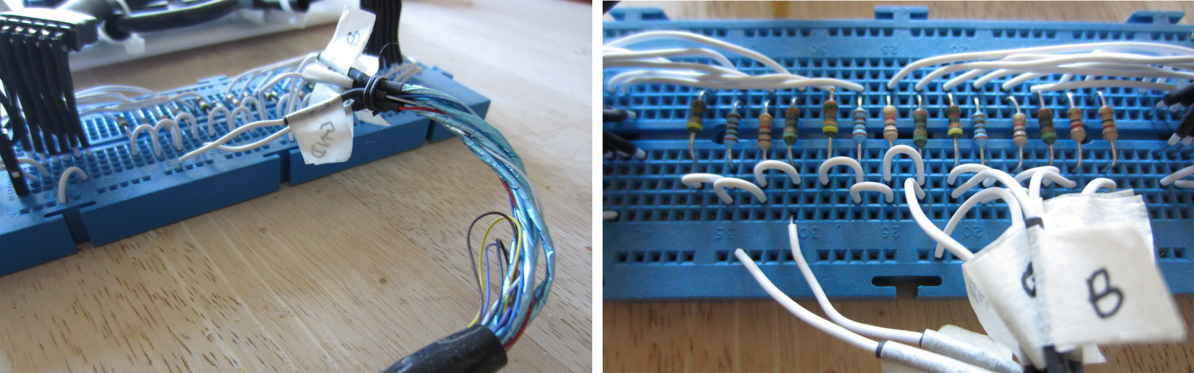
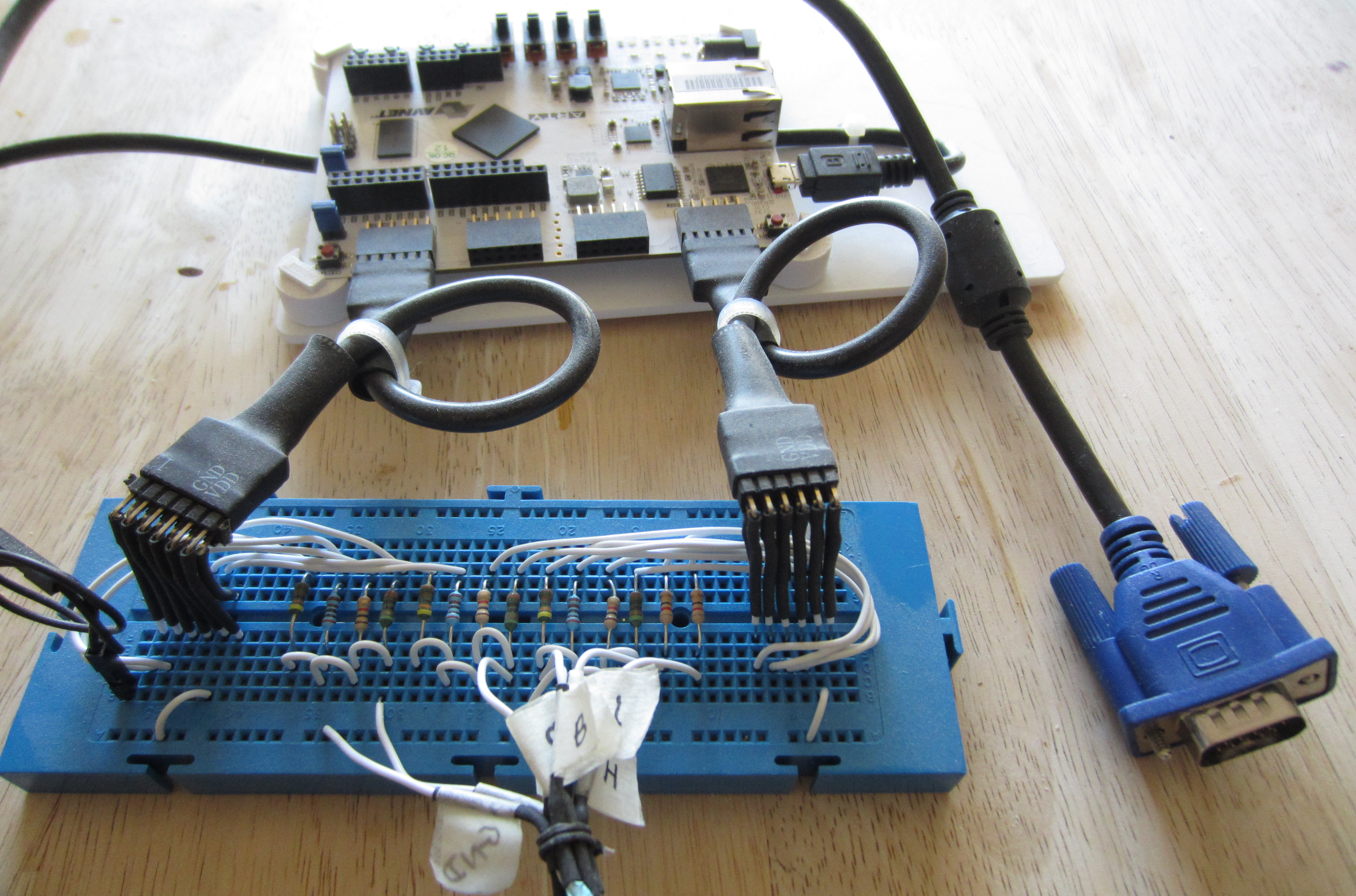
Figure 14 : Arty board prototype
A nice feature of the Xilinx tool set is that you can initialise any memory element in the FPGA at boot e.g. flip-flops, BlockRAMs etc. Therefore, the first test was to load into the frame the test pattern shown in figure 15. This is a 160 x 120 image marking the corners and displaying the three primary colours. The original test image is available here: (Link).
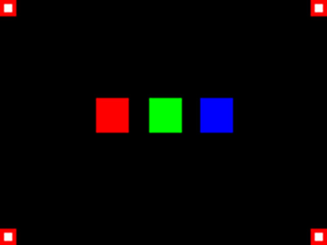
Figure 15 : video test pattern
To convert this image into a BlockRAM configuration file i wrote some simple python code.
Then it was just a "simple" task of downloading the configuration, honest it work first time :). No, there were lotssss of errors, but got there in the end :(.
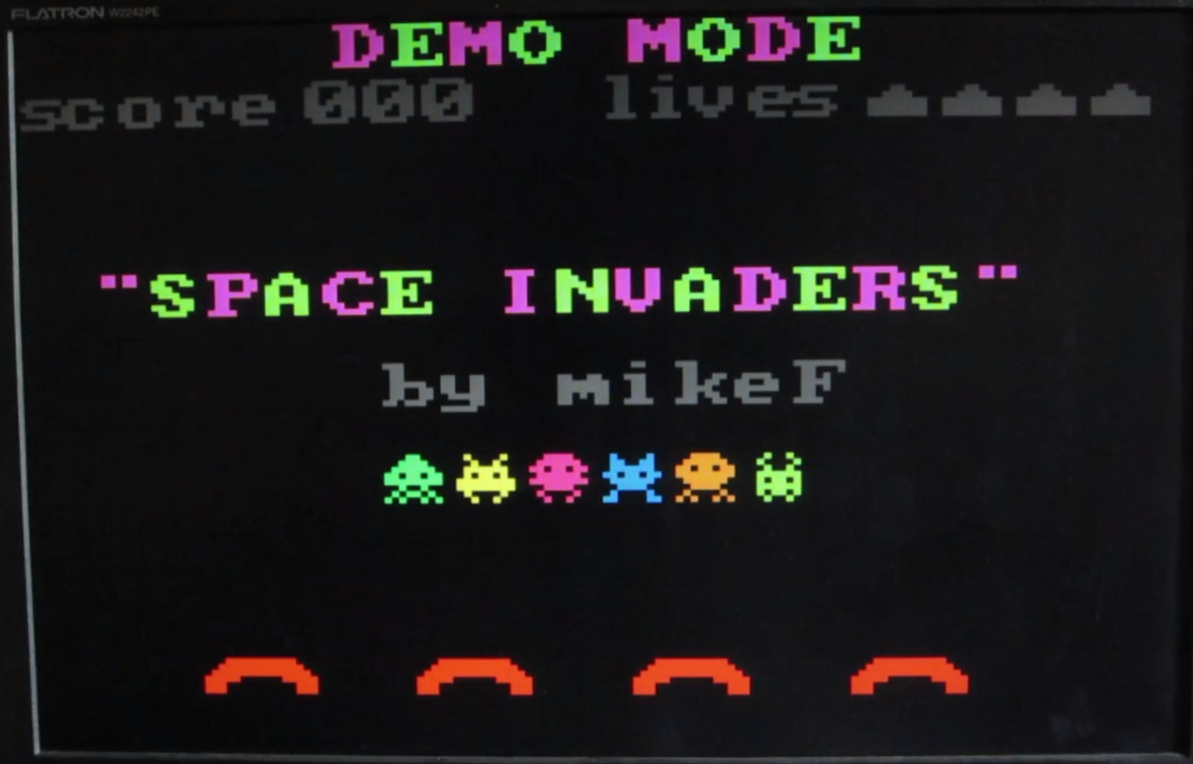
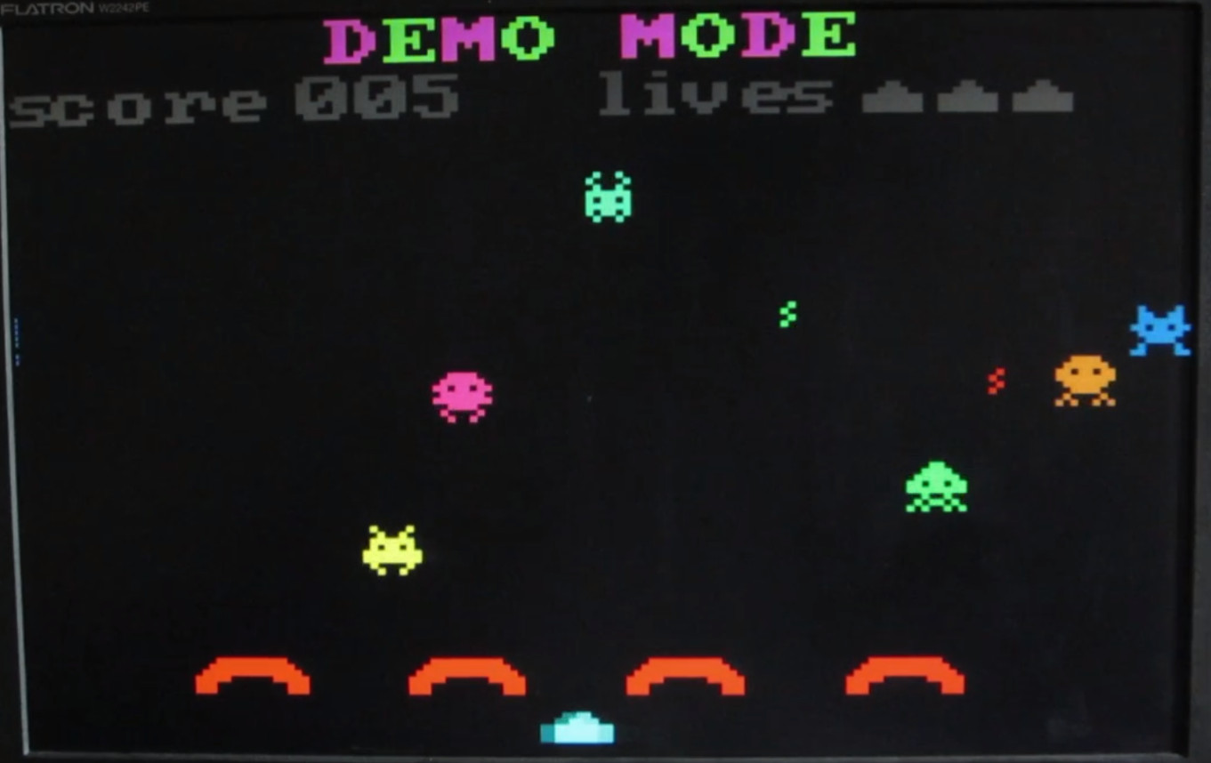
Figure 16 : "Space Invader"
A video of the "Space Invaders" demo in action is available here: (Link), demonstrating sprite movement, limit detection, collision detection and simple animation.

This work is licensed under a Creative Commons Attribution-NonCommercial-NoDerivatives 4.0 International License.
Contact email: mike@simplecpudesign.com