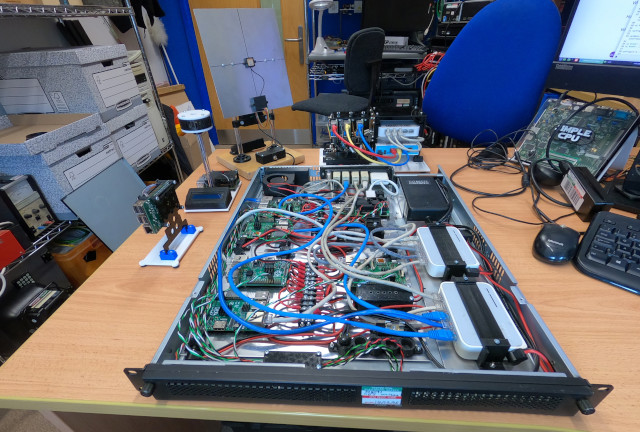
Figure 1 : hardware - welcome to my world (well for the moment)
A new year, a new module SYS2 (Networking), well not so new i originally developed the material for this module a few years ago. Back then it was called SYS4, a second year module taught in the third year (i know) an introductory module on basic networking. This material was then used by other people. Note, the old SYS4 should not to confused with today's SYS4 which details with IoT. Today, a few years later and a move from trimesters to semesters i've come back to teaching networking. However, this time its a combined module: operating systems and networking. I know dumping these two topics together is quite common in academia, BUT, they are completely different topics, one focuses on software and hardware, the other deals with protocols. Fortunately, in the new SYS2 module these are separate strands, in my opinion trying to force these two topics into a single strand would not be the best idea, sometimes things just don't fit no matter how hard you push :).
The SYS2 (Networking) strand was designed and taught based on feedback from our industrial partners. A common point raised was that our students know the theory, the key words, but lacked the hands on skills and knowledge needed to use, configure and write software for networks. Also, I consider myself to be a network engineer i.e. i have built and debugged a few networks in my time. I confess i'm not really interested in analysing the probability of a network packet passing through a congested network, i would rather build and analyse real networks, therefore, that was the starting point SYS2 (Networking). The core design elements that the SYS2 (Networking) strand is built around are:
You don't learn these types of skills from a book, or by using a simulator, you learn these skills by doing, by interacting with actual hardware, from hands on experience of real networks. Not to say that books and simulators aren't useful resources and tools that can aid you on your journey to becoming a network engineer, but you can't experience this journey if you never seen or used actual hardware. Unfortunately, hardware and the space needed to use it are in short supply at the moment in the department, with the eternal pressures to save money, so appreciate this hardware whilst its still have it :). Figure 1 illustrates the different hardware we will be using in this module, at its core is the Raspberry Pi, the ubiquitous single board computer (SBC). The aim of this hardware is to create a network of hosts, as shown in figure 2, a collection of processing nodes that can communicate across a "network", each performing a different function, each requiring a different protocol to allow them to perform their designated role.
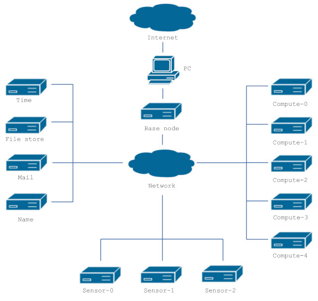
Figure 2 : the "network"
A brief overview / description of this hardware and links to more in-depth mumbles of how each piece of hardware was made can be found below:
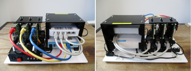

Figure 3 : Raspberry Pi base system, front (left), back (right), power supply (bottom)
The main teaching platform used in this module is the Base node, as shown in figure 3. This was developed to ensure that the network equipment used in this module does not interfere with, or create security issues on the department's main network. The lab PCs can connect to a Base node via its spare Ethernet port, allowing them to access to: 3 x Raspberry Pi4, 1 x switch and 1 x router. The aim of the Base node is that initially students can create self contained networks, build different networks between the three Raspberry Pi4s, without the need for external hardware. Then once they have had the chance to gain a basic understanding of how a network works they can connect this system to other Base nodes to form bigger networks, or to the lab's internal network to access other network resources e.g. mail server, file server, time server, compute nodes etc, to build larger, more complex networks. For more information on how this system was built, configured and programmed : Link.
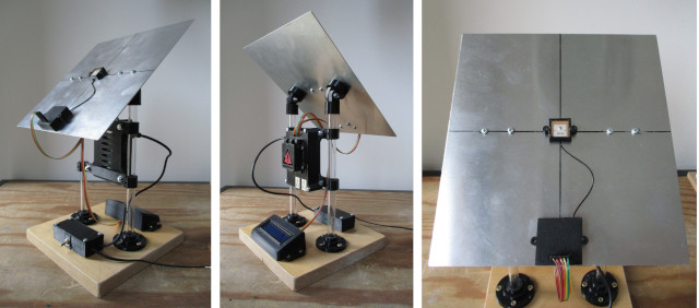
Figure 4 : Time node
Owing to security concerns i.e. the Raspberry Pis run wireshark to analyse network traffic, the Base nodes do not have access to the Internet. This is not a big issue, but it does mean they can not access time servers to find out what the time is. Therefore, this host uses a NEO-6 GPS receiver to obtain GPS time, a time based on atomic clocks contained within GPS satellites orbiting the earth. This data is then used to synchronise a Network Time Protocol (NTP) server running on the Raspberry Pi, allowing other hosts on the network to synchronise their times to this reference time. For more information on how this system was built, configured and programmed : Link.
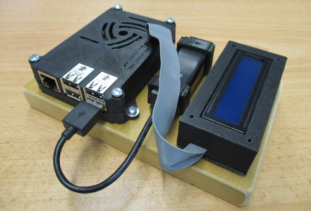
Figure 5 : Name node
As the hosts in the lab don't have access to the Internet, they don't have access to the department's DNS name servers. I could hard code each hosts name in the host file on each machine, but thats not the most flexible solution. At the other end of the spectrum code install BIND on each Base node and define a separate DNS zone for each desk. However, in the end i went for a solution that was somewhere in the middle by using the MikroTik DNS server and Pi-hole. For more information on how this system was built, configured and programmed : Link.
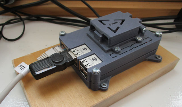
Figure 6 : File node
A fundamental requirement of any network is to transfer files from one host to another. Back in the early days of the Internet this functionality was centralised as a File Server: Link, a server that you could upload files to and download files from. In this file server we will be using a range of different network protocols, some encrypted and some not e.g. File Transfer Protocol (FTP), Secure File Transfer Protocol (SFTP) and Hypertext Transfer Protocol (HTTP). For more information on there protocols refer to: FTP, SFTP and HTTP. For more information on how this system was built, configured and programmed : Link.
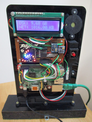
Figure 7 : Ping node
This node is just for fun, made from spare parts. Its main purpose is to beep and flash when pinged, an interact lab "toy" :). For more information on how this system was built, configured and programmed : Link.
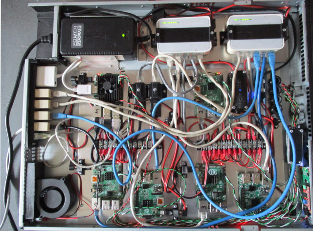
Figure 8 : 1U rack of Raspberry Pis
To simplify the construction of the "network" shown in figure 2, the network's core hardware has been implemented in a 1U rack, shown in figure 8. Note, this is on a shelve in my office so i can give it a kick if needed, therefore, a key requirement was that it was as quite as i could make it i.e. ideally no fans. This hardware contains two of the network's core components: mail server and file server. In addition to these the rack also contains generic "compute nodes". These nodes don't perform any specific role, but do generate additional network traffic that creates a "richer", more interesting network when analysing network traffic. For more information on how this system was built, configured and programmed : Link.
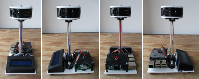
Figure 9 : Sensor node - version 1.
To add some real time data sources to the network i designed some sensor nodes that can measure a room's temperature, humidity and atmospheric pressure. These sensors are mounted in a "pod" approximately 120 mm above the Raspberry Pi i.e. to minimise the heating effect produced by the electronics below. There was also a secondary aim here, to allow me to measure and record the temperature in my office and in the lab, as i would argue that the temperatures in the summer are a little on the hot side :). Confess to save time i simplified the design for some of the sensor nodes, as shown in figure 10. These reuse some spare parts made for a Base node prototype. These have the same sensors, but are missing the LCD and the pod. However, there is 3D printed barrier between the sensors and the electronics, so hopefully the hotness of the Raspberry Pi will not affect the sensor data, maybe :). For more information on how this system was built, configured and programmed : Link.

Figure 10 : Sensor node - version 2.
WORK IN PROGRESS

This work is licensed under a Creative Commons Attribution-NonCommercial-NoDerivatives 4.0 International License.
Contact email: mike@simplecpudesign.com